Pop-up drain stopper linkage assembly

a technology of linkage and drain stopper, which is applied in the field of linkage assembly, can solve the problems of inability to work the lift rod, the structure above is not easy to assemble, and the work is arduous and time-consuming, so as to improve the convenience of assembling, quick and convenient assembly, and the effect of quick plugged

Active Publication Date: 2010-03-04
GLOBE UNION INDAL
View PDF6 Cites 12 Cited by
  • Summary
  • Abstract
  • Description
  • Claims
  • Application Information

AI Technical Summary

Benefits of technology

[0016]Accordingly, the lift rod can be quickly plugged into the connecting bar for positioning, and the pivot rod can be received and fixed by the connecting bar for positioning, so as to achieve the object of quickly and conveniently assembly. Besides, the fixed portion on the pivot rod can be received and fixed within the hole of the connecting bar for positioning, so as to achieve the object of certain linkage between the lift rod, the connecting bar and the pivot rod.
[0

Problems solved by technology

However, the above-mentioned structure is not easy for assembling because this kind of structure is normally set up in the narrow and small spaces under the washbasin.
To assemble the lift rod, the pivot rod and the connector in such small spaces, and to lock the bolt of the connector by the screwdrivers, such works are arduous and time-consuming.
Moreover, the bolt of the above-mentioned connector may become loose after using over a long period

Method used


Image

  • Pop-up drain stopper linkage assembly
  • Pop-up drain stopper linkage assembly
  • Pop-up drain stopper linkage assembly

Examples


Embodiment Construction

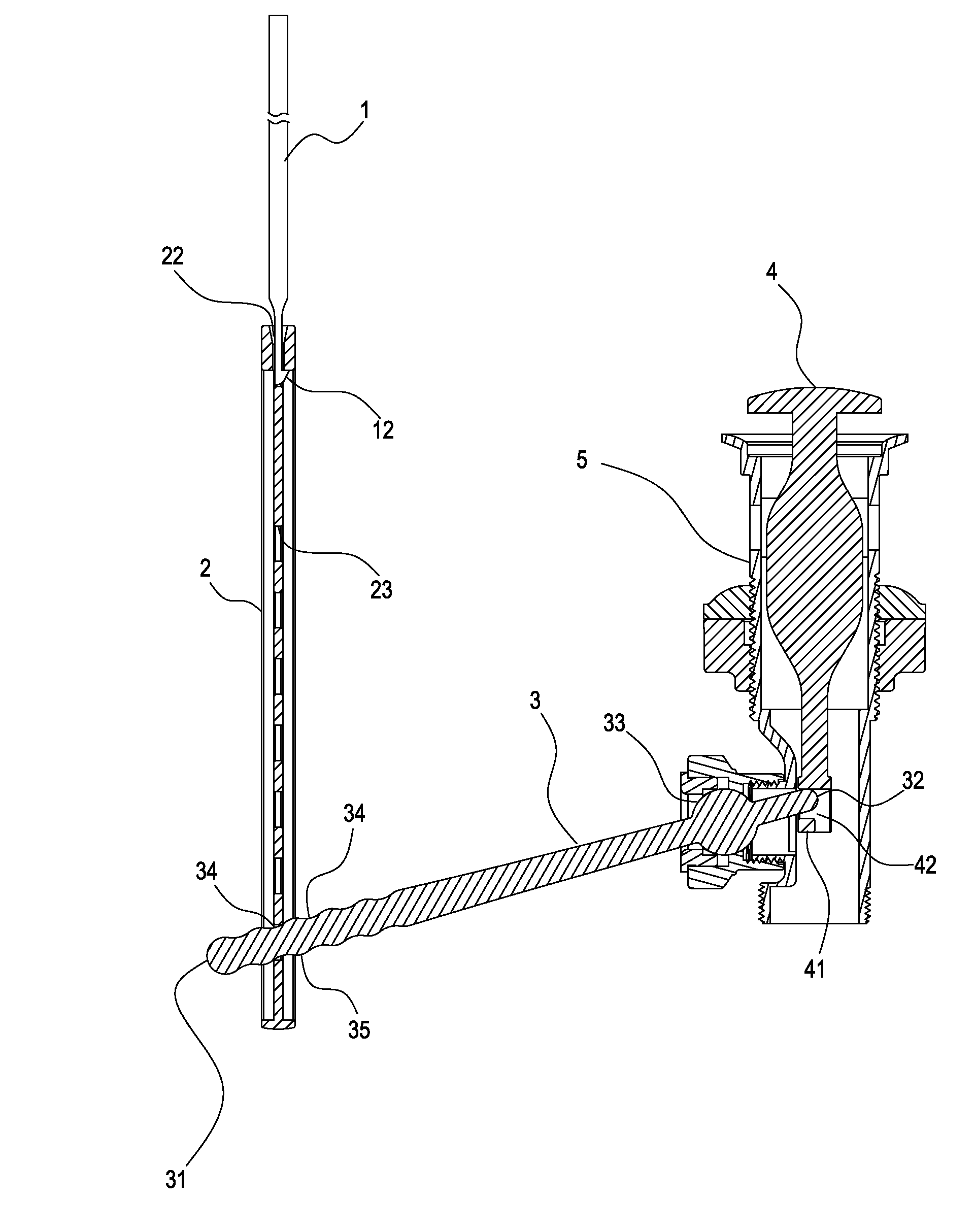
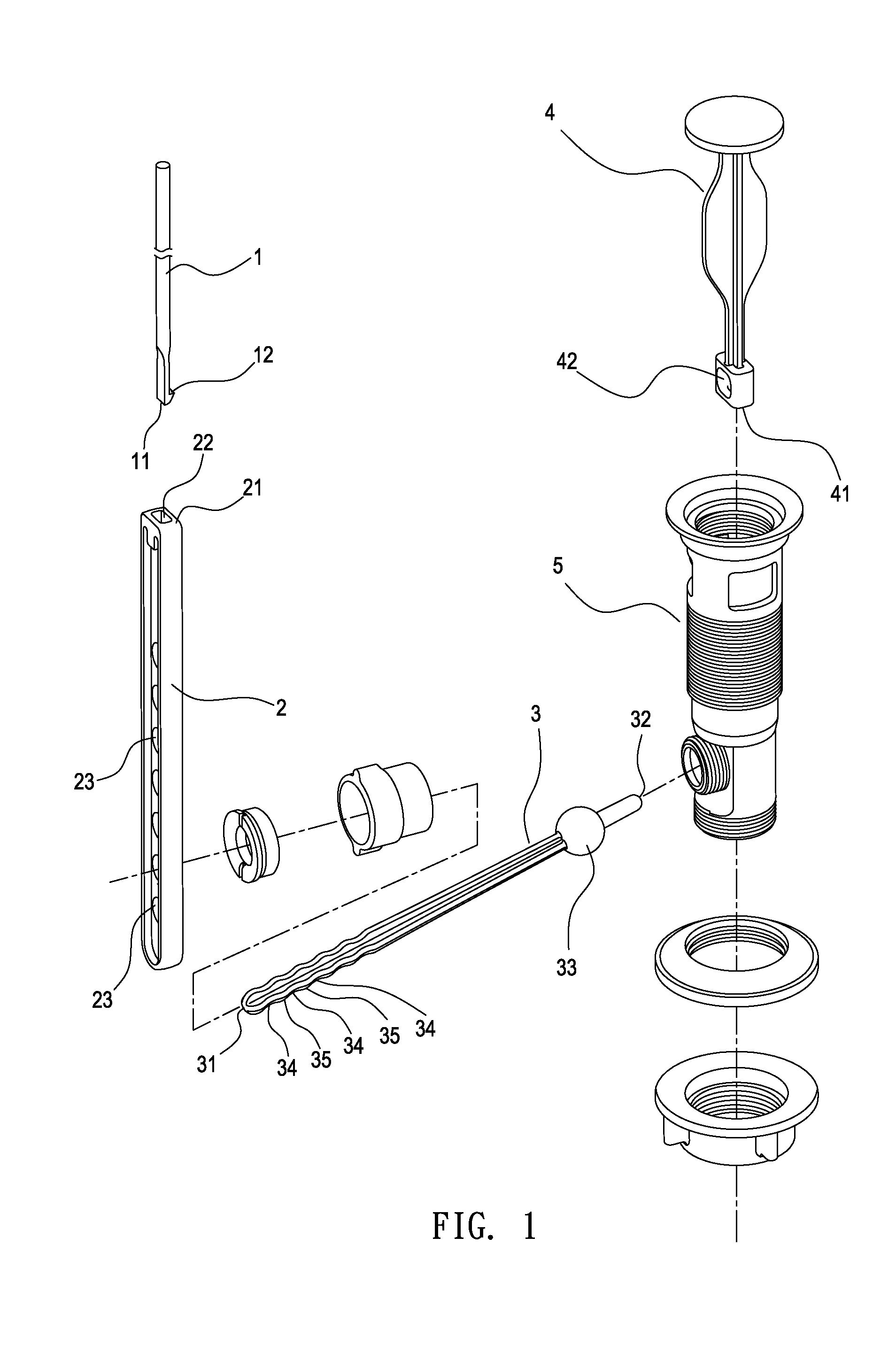
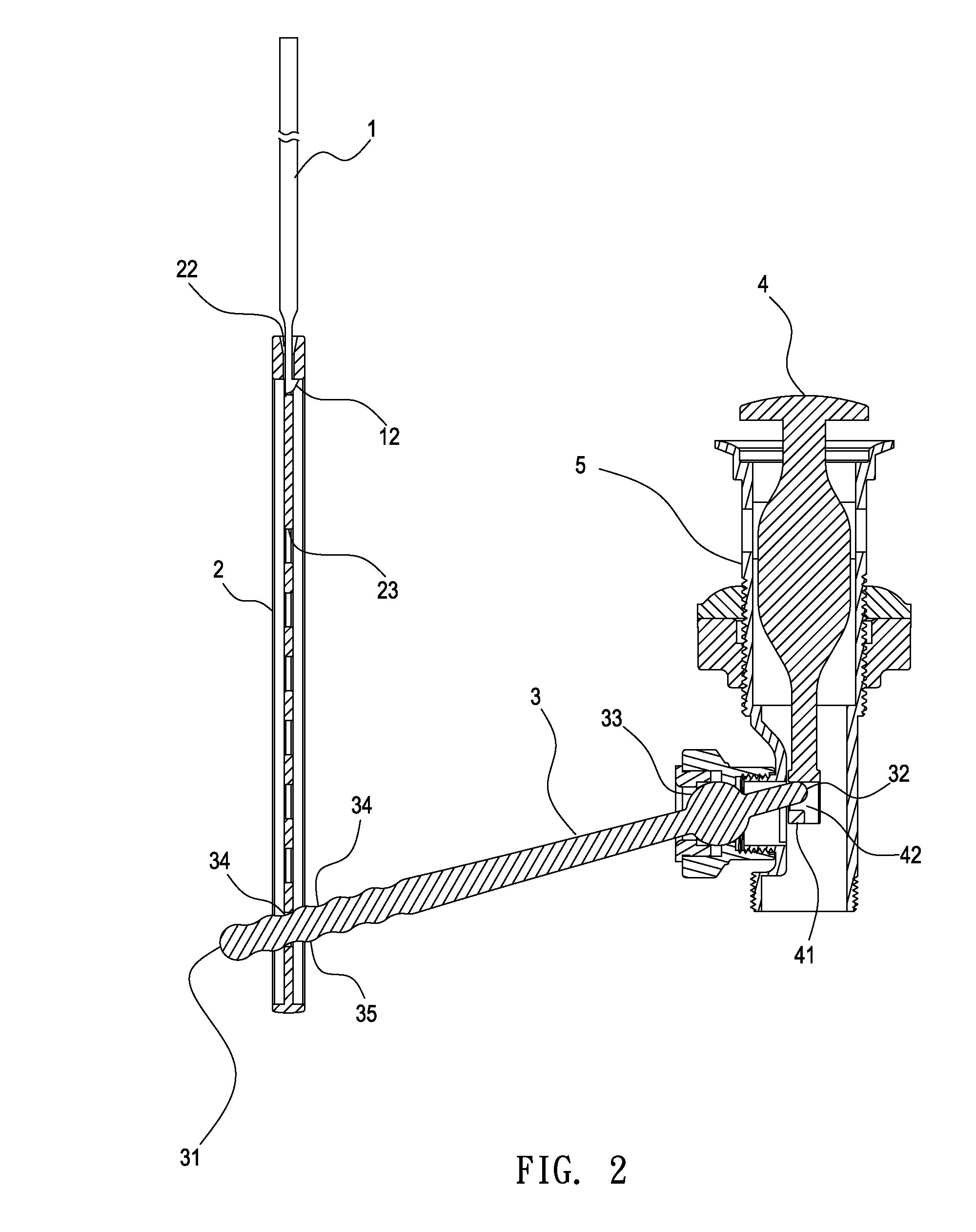
[0021]Refer to FIG. 1 and FIG. 2, which shows a preferred embodiment according to the present invention. FIG. 1 is a schematic view according to the present invention and FIG. 2 is a cross-sectional view of the present invention.

[0022]The pop-up drain stopper linkage assembly according to the present invention includes a lift rod 1, a connecting bar 2, a pivot rod 3 and a drain stopper 4. The pivot rod 3 and a drain stopper 4 are disposed in the drain base 5. The way to dispose the pivot rod 3 and the drain stopper 4 in the drain base 5 is well-know in the prior art, so that the disposing method will not be mentioned here.

[0023]The lift rod 1 has a bottom end 11, and the bottom end 11 forms an engagement part 12. In this embodiment, the engagement part 12 has a hook-shaped configuration and the engagement part 12 has a substantially rectangular cross-section. In practical operation, the lift rod is disposed through the faucet housing. (Un-shown in the FIG)

[0024]The connecting bar 2 ...


PUM


Abstract

A pop-up drain stopper linkage assembly includes a lift rod, a connecting bar, a pivot rod and a drain stopper. The bottom end of the lift rod forms an engagement part. The upper end of the connecting bar has an engagement groove for the engagement part of the lift rod being engaged and fixed, and the connecting bar has a plurality of holes spaced apart a distance away from the engagement groove. The second end of the pivot rod connects to the drain stopper and a section adjacent the first end has a plurality of fixed portions for tying in with the hole of the connecting bar, and each of the fixed portions and any one of the holes are capable of being passing through and positioning with each other. Thereby, the pop-up drain stopper linkage assembly can be quickly and conveniently assembled with reliable linking effect.

Description

BACKGROUND OF THE INVENTION[0001]1. Field of Invention[0002]The present invention relates to a linkage assembly, and more particularly to a pop-up drain stopper linkage assembly which is easy to be quickly assembled and capable of linking reliably.[0003]2. Related Art[0004]Generally, the washbasin used in most family has a lift rod extended downward from the faucet housing, which the lift rod connects to a pivot rod and the pivot rod connects to the pop-up drain stopper, the pop-up drain stopper can then be driven to open or close by pulling the lift rod up and down, so as to save the water in the washbasin or move the water out from the washbasin.[0005]The pivot rod mentioned above usually fixes with a spherical body, which the spherical body is pivoted in the drain base. The pivot rod can act a lever motion based on the spherical body as a pivot point, so as to drive the pop-up drain stopper move up or down and further to achieve the operation of open or close. More specific, the ...

Claims


Application Information

Patent Timeline
IPC IPC(8): E03C1/23
CPCE03C1/2302E03C1/23
Inventor LI, CHUN-HUNGHSU, WEI-MIENWU, YONGJUN
Owner GLOBE UNION INDAL
Why Eureka
Try Eureka