Fuel cell manufacturing method, fuel cell separator, and transportation system of the same

a technology of fuel cell separator and manufacturing method, which is applied in the manufacture of cell components, final product details, cell components, etc., can solve the problems of particulate and inability to perform optical positioning, and achieve the effect of more accurate and rapid positioning

Inactive Publication Date: 2010-03-04
TOYOTA JIDOSHA KK
View PDF6 Cites 7 Cited by
  • Summary
  • Abstract
  • Description
  • Claims
  • Application Information

AI Technical Summary

Benefits of technology

[0017]Still further, in order to achieve the above-mentioned object, a transportation system of a fuel cell separator according to a preferred embodiment of the present invention includes a suction hand having a suction surface corresponding to concave and convex portions on a surface of the fuel cell separator, and a sensor optically reading a positioning mark provided on the fuel cell separator. The position and the direction of the fuel cell separator is controlled by the suction hand that adsorbs the fuel cell separator based on the positioning mark read by the sensor, thereby positioning the fuel cell separator in place.
[0018]According to the present invention, a technology of optically positioning a fuel cell separator is provided. For example, according to a preferred embodiment of the present invention, it is possible, when necessary, to perform positioning more accurately and rapidly than when positioning is performed by, for example, fitting a penetration pin in a through-hole.

Problems solved by technology

The technology disclosed in Patent Document 3, in particular, is not capable of performing optical positioning.

Method used


Image

  • Fuel cell manufacturing method, fuel cell separator, and transportation system of the same
  • Fuel cell manufacturing method, fuel cell separator, and transportation system of the same
  • Fuel cell manufacturing method, fuel cell separator, and transportation system of the same

Examples


Embodiment Construction

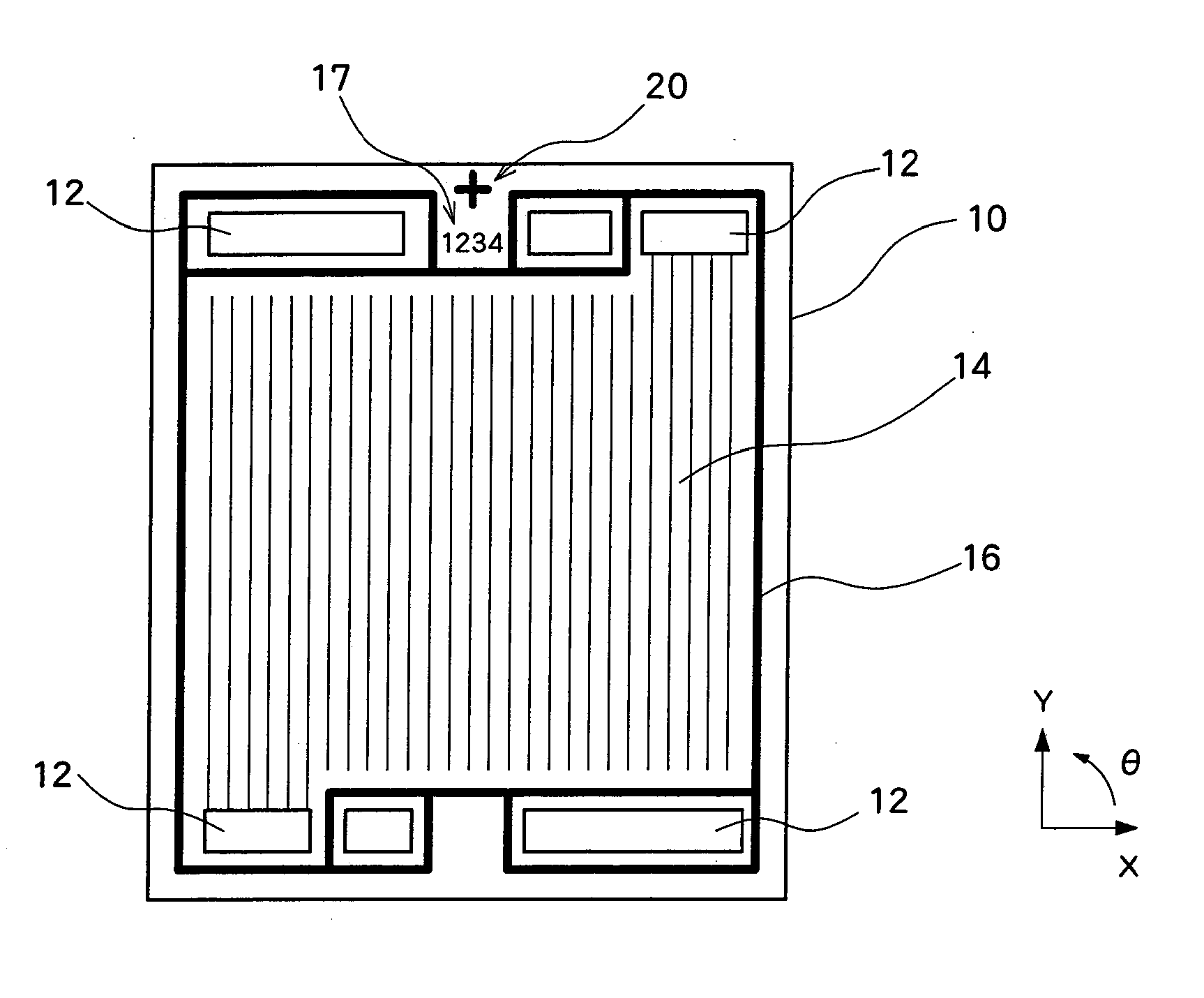
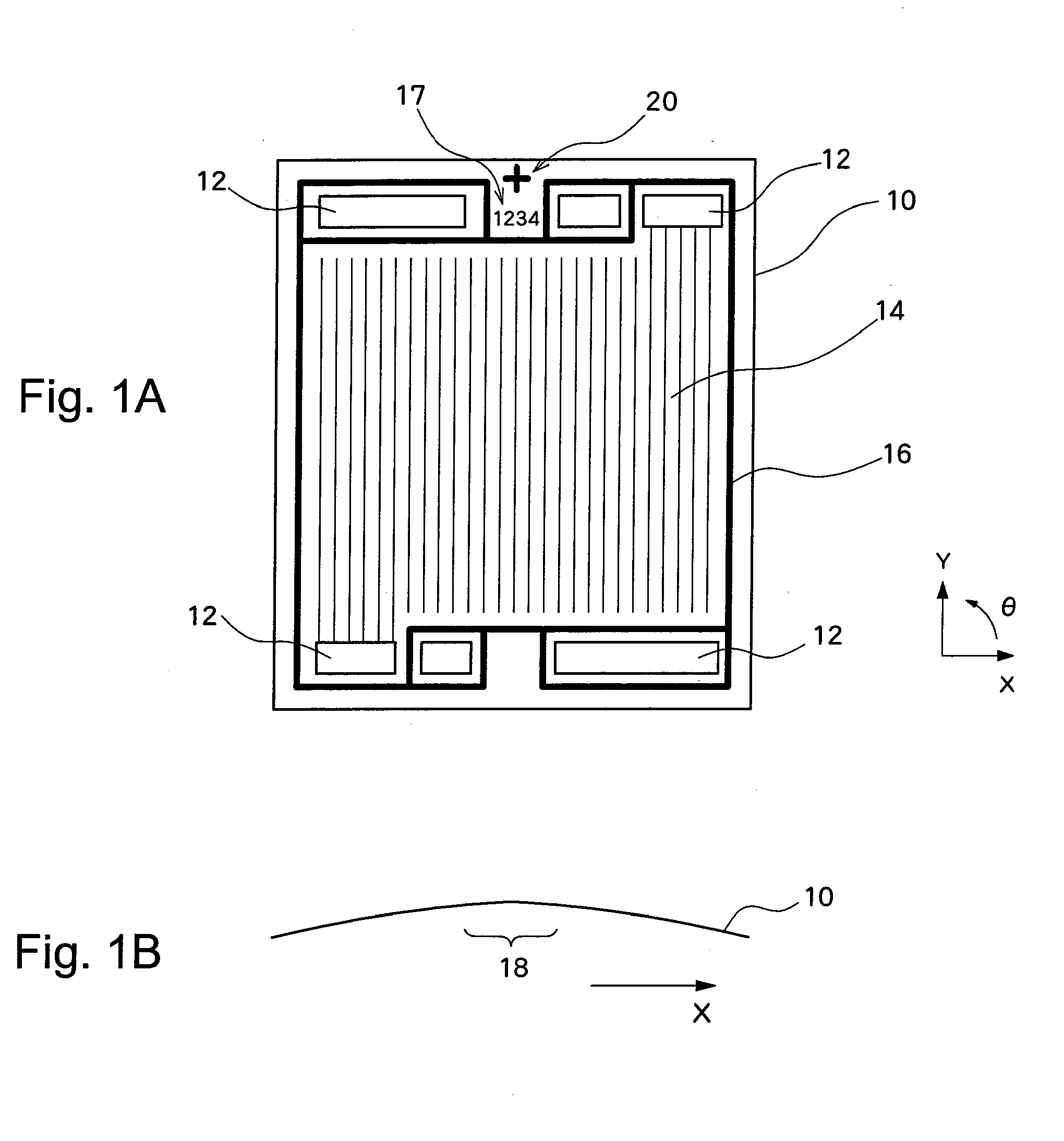
[0023]FIGS. 1 through 4 illustrate a preferred embodiment of the present invention. The preferred embodiment of the present invention will be described hereinafter referring to these figures.

[0024]FIG. 1 shows an example fuel cell separator according to the preferred embodiment of the present invention. FIG. 1 shows a separator 10 used in a fuel cell. The separator 10 is a plate-shaped member having front and rear surfaces both in an approximately rectangular shape, and is made of an electroconductive material such as an SUS material or carbon. Two separators 10 tightly hold an MEA in between, thereby forming a battery cell. A plurality of battery cells are then stacked, thereby forming a fuel cell.

[0025]FIG. 1(A) is a schematic view of the front surface of the separator 10. In a center region on the approximate rectangle surface, the separator 10 has a flow path 14 through which fluid flows. The flow path 14 is provided along the Y-axis direction. The region in which this flow path...


PUM

PropertyMeasurementUnit
shapeaaaaaaaaaa
chemical energyaaaaaaaaaa
electrical energyaaaaaaaaaa

Abstract

A positioning mark (20) has a shape by which a position and a direction can be identified when moved together with a separator (10) along a plane. In other words, the positioning mark (20) is formed, for example, in a cross shape so that a position on the X-axis and a position on the Y-axis and the tilt in the θ direction of the positioning mark (20) can be identified. The positioning mark (20) is optically read by, for example, a sensor, and the positions on the x-axis and the Y-axis of the positioning mark (20) are calculated by, for example, image analysis processing. Based on the calculation result, positioning of the separator (10) is performed.

Description

TECHNICAL FIELD[0001]The present invention relates to a fuel cell manufacturing method, and to a fuel cell separator and its transportation system, and particularly to a technology of positioning a fuel cell separator.BACKGROUND ART[0002]Fuel cells in which fuel gases such as easily-oxidizable hydrogen are reacted with oxygen in the air and the obtained chemical energy is converted into electrical energy are well known. Generally, such fuel cells are formed using a plurality of battery cells which perform the above-mentioned chemical reaction. For example, a fuel cell employing flat battery cells is known. Here, the flat battery cells have a stacking structure in which separators made of electroconductive materials (for example, metals) are disposed on both sides of a plate-shaped membrane electrode assembly (MEA). A plurality of flat battery cells are stacked to form a cell stack to thereby form a fuel cell.[0003]When the battery cell and the cell stack with the above-described str...

Claims


Application Information

Patent Timeline
Patent Type & Authority Applications(United States)
IPC IPC(8): H01M8/02H01M2/14
CPCH01M8/0247H01M8/1002Y10T29/49108Y02E60/521Y10T29/53135H01M8/241H01M8/0258H01M8/1007H01M8/2404H01M8/2483Y02E60/50Y02P70/50H01M8/02H01M8/04H01M8/24
Inventor FUKAYA, YOSUKE
Owner TOYOTA JIDOSHA KK
Why Eureka
Try Eureka