Air Cushion shoe sole

a technology of shoe sole and air cushion, which is applied in the field of air cushion shoe sole, can solve the problems of excessive manufacturing cost, wearer discomfort, and shoe rupture, and achieve the effects of reducing manufacturing costs, reducing the total volume of the shoe sole, and reducing the weight of the sho

Inactive Publication Date: 2010-03-04
KIM YOUNG SEOK
View PDF7 Cites 59 Cited by
  • Summary
  • Abstract
  • Description
  • Claims
  • Application Information

AI Technical Summary

Benefits of technology

[0021]As described above, the air cushion shoe sole according to the present invention has significant advantages over previously known shoe sole. In the air cushion shoe sole according to the present invention, the plurality of air pockets and the air chamber having the air passageway are provided in the main body of the shoe sole, and the hardened reinforcement sheet is positioned onto the upper surface of the main body in a manner that it has an extended warranty to cover the open upper portion of air passageway and the open upper portions of the air pockets. Due to the constitution of the shoe sole as described above, the air may be collected in the air chamber at first and then it may be introduced into the interior of the shoe via the hardened reinforcement sheet and the shoe liner. Due to the existence of the air chamber, the air pockets and the air passageway, total volume of the shoe sole may be reduced and thereby resulting in weight reduction of the shoe. Also, it gives a considerable reduction in manufacturing costs.
[0022]By virtue of the manufacture of the main body of the shoe sole, which can be made of a foam rubber, while affording the same shock absorbing effect, the damage of the shoe sole can be substantially less than was hitherto the case. By virtue of simple installation of the non-slip cushion sheet at the bottom surface of the shoe sole, total structure of the shoe sole can be substantially simpler than was hitherto the case. By virtue of simple installation of the nonskid member at the bottom surface of the shoe sole, it is possible to prevent the foot of a wearer from slipping during the entire walking gait cycle of the wearer, thereby providing good bottom support, elastic air cushioning and shock-absorbing effects for relieving foot pressure.

Problems solved by technology

One drawback of using the air bag or the shock-absorbing spring is that the manufacturing process may require a large number of parts and additional manufacturing steps, thereby resulting in the generation of excess manufacturing cost.
Another drawback of such known shoe sole is that the shock-absorbing spring made of a metal material is apt to damage the shoe sole and thereby resulting in the rupture of the shoe.
Another drawback of such known shoe sole is that the shock-absorbing spring made of a metal material is apt to generate an unbearable noise and thereby it gives the wearer an unpleasant feeling during the entire walking gait cycle of a wearer.

Method used


Image

  • Air Cushion shoe sole
  • Air Cushion shoe sole
  • Air Cushion shoe sole

Examples


Embodiment Construction

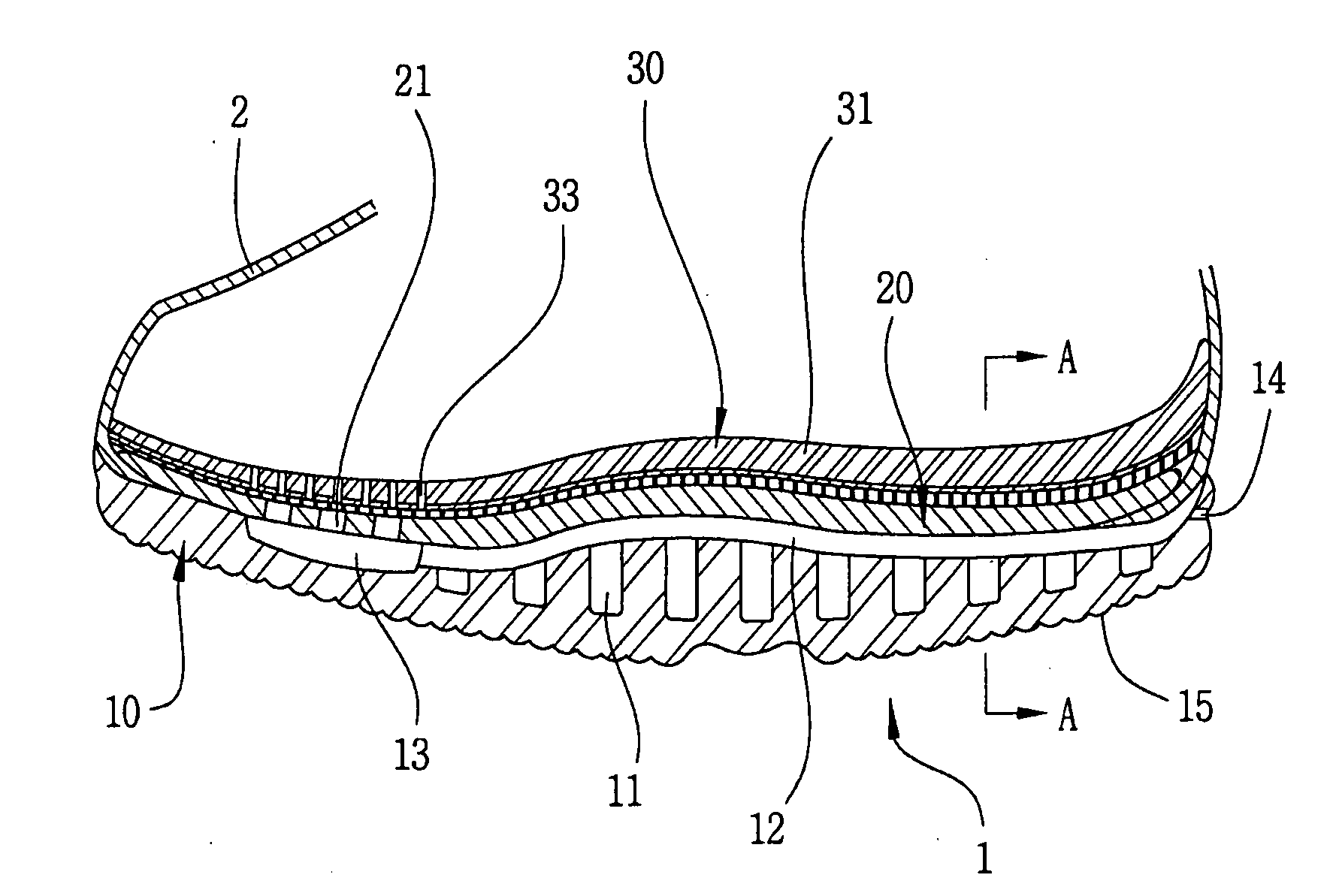
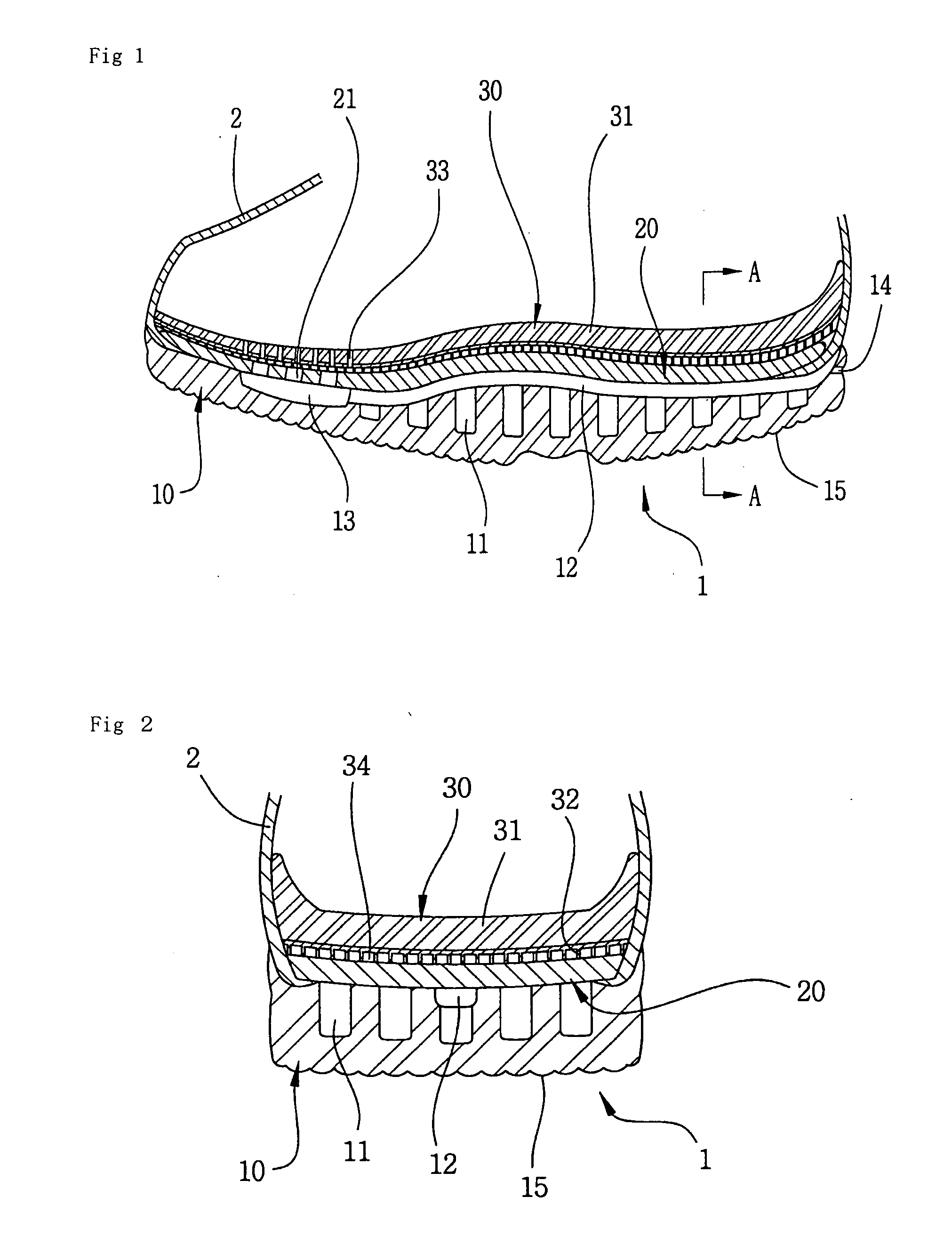
[0031]Hereinafter, the constitution and the operation of an air cushion shoe sole according to the preferred embodiment of the present invention will be explained in more detail with reference to the accompanying drawings FIGS. 1 to 7.

[0032]Prior to proceeding to the more detailed description of the preferred embodiment according to the present invention, it should be noted that, for the sake of clarity and understanding of the invention identical components which have identical functions have been identified with identical reference numerals throughout the different views which are illustrated in each of the attached drawing Figures.

[0033]As will be best seen in FIGS. 1 and 2, this invention relates to the air cushion shoe sole 1 has a substantially arc shape on the whole of which front and rear portions are slanted upwards at a predetermined angle of inclination. The shoe sole 1 comprises a hardened reinforcement sheet 20 which is disposed onto the upper surface of a main body 10 ...


PUM


Abstract

An air cushion shoe has an air chamber at an upper surface of a front side of a main body. An air passageway extends from the air chamber to an air inlet. Air pockets are formed in the main body at predetermined positions below the air passageway. First air vents are formed at a front side of the hardened reinforcement sheet positioned onto the main body to cover the open upper portions of the air passageway and the air pockets. Second air vents are formed at a front side of a main body of a shoe liner. A cushioning material having a honeycomb structured body is formed at the bottom surface of the main body.

Description

BACKGROUND OF THE INVENTION[0001]1. Field of the Invention[0002]The present invention relates generally to an air cushion shoe sole, and more particularly to an air cushion shoe sole capable of providing good elastic air cushioning and shock-absorbing effects for relieving foot pressure during the entire walking gait cycle of a wearer, wherein an air chamber is formed in an upper surface of the front side of the main body, wherein an air passageway extends from the rear side of the air chamber to an air inlet formed at a rear side edge of the shoe sole, wherein pluralities of air pockets are formed in the main body at predetermined positions below the air passageway, wherein pluralities of first air vents are formed at the front side of a hardened reinforcement sheet, in which the hardened reinforcement sheet is positioned onto the upper surface of the main body in a manner that it has an extended warranty to cover the open upper portion of air passageway and the open upper portions...

Claims


Application Information

Patent Timeline
Patent Type & Authority Applications(United States)
IPC IPC(8): A43B13/20A43B13/12A43C15/00
CPCA43B7/081A43B7/1445A43B13/10A43B13/12A43B13/145A43B13/203A43B13/24A43B1/0009A43B13/148A43B13/18A43B13/20
Inventor KIM, YOUNG SEOK
Owner KIM YOUNG SEOK
Why Eureka
Try Eureka