Eureka AIR delivers breakthrough ideas for toughest innovation challenges, trusted by R&D personnel around the world.

Telescopic mast having reduced play

a technology of telescopic masts and telescoping sections, which is applied in the direction of shores, mechanical devices, rod connections, etc., can solve the problems that none of these inventions are adequately fulfilling the requirements of stability and accuracy, and achieve the effect of minimising the play between the telescoping sections and great accuracy

Active Publication Date: 2010-03-04
DRS SUSTAINMENT SYST
View PDF33 Cites 12 Cited by
  • Summary
  • Abstract
  • Description
  • Claims
  • Application Information

AI Technical Summary

Benefits of technology

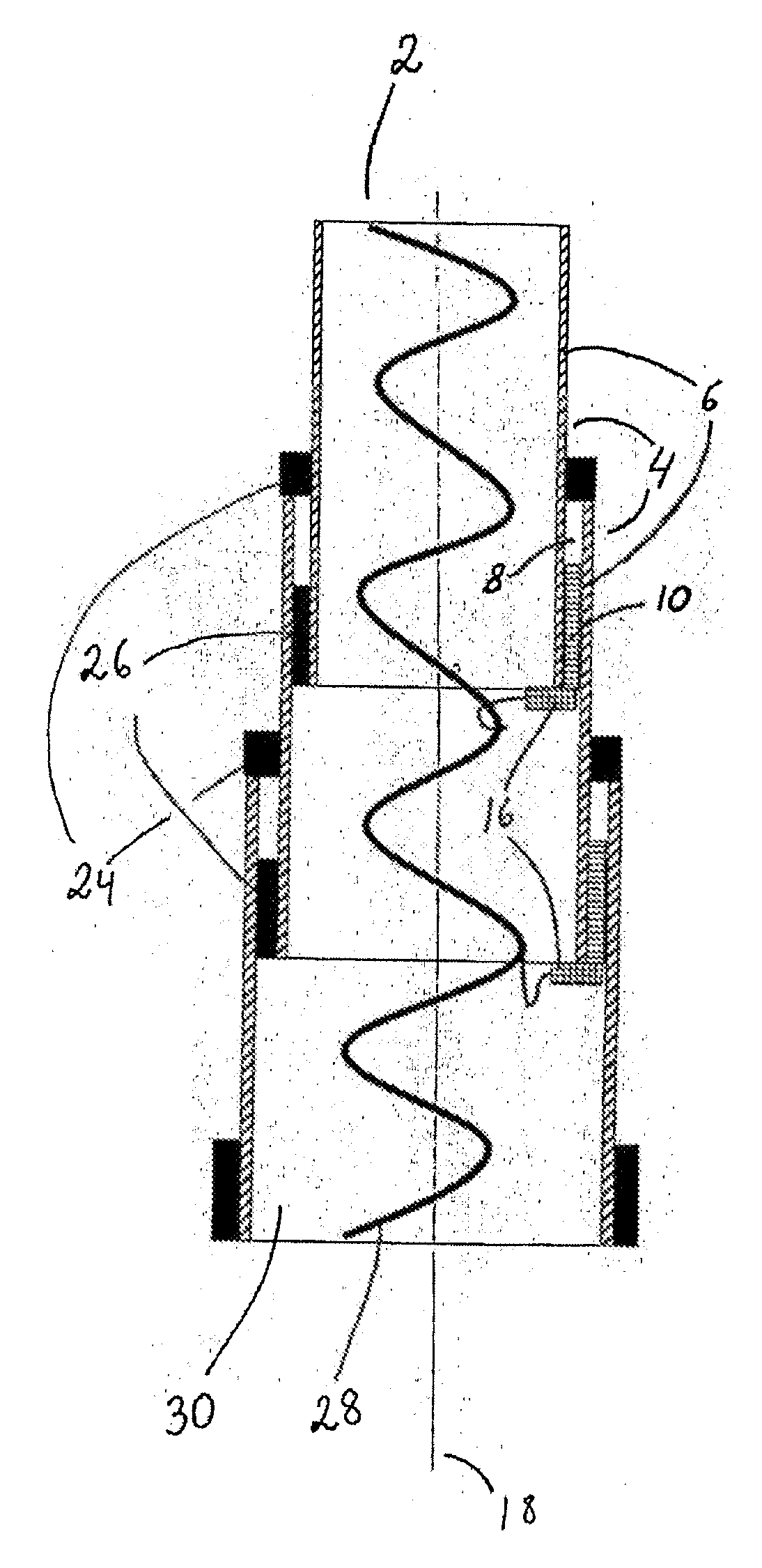
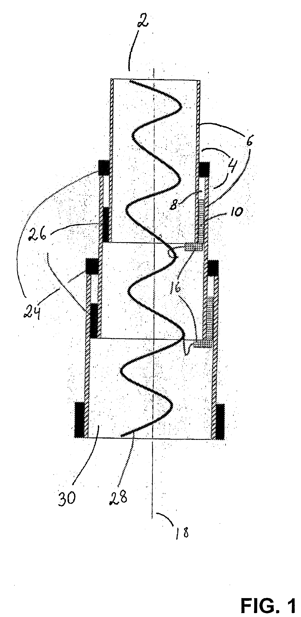
[0004]The object of the present invention is to provide a telescopic mast where the play between the telescoping sections is minimised. It is a further object of the invention to provide a telescopic mast that may be positioned with great accuracy.DESCRIPTION OF THE INVENTION
[0006]By a telescopic mast according to the invention is thus achieved a number of advantages, as the means pressing the adjacent walls away from each other minimises the play occurring between adjacent telescoping sections. By pressing the adjacent walls away from each other, the play is eliminated or minimised.
[0007]Means of different nature with regard to design as well as material may be used. It may be advantageous to make the means of materials that are dimensionally stable in connection with large temperature fluctuations. It may furthermore be advantageous to coat the means with a layer of friction reducing material, as e.g. Teflon, for minimising friction between and wear of the elements involved.
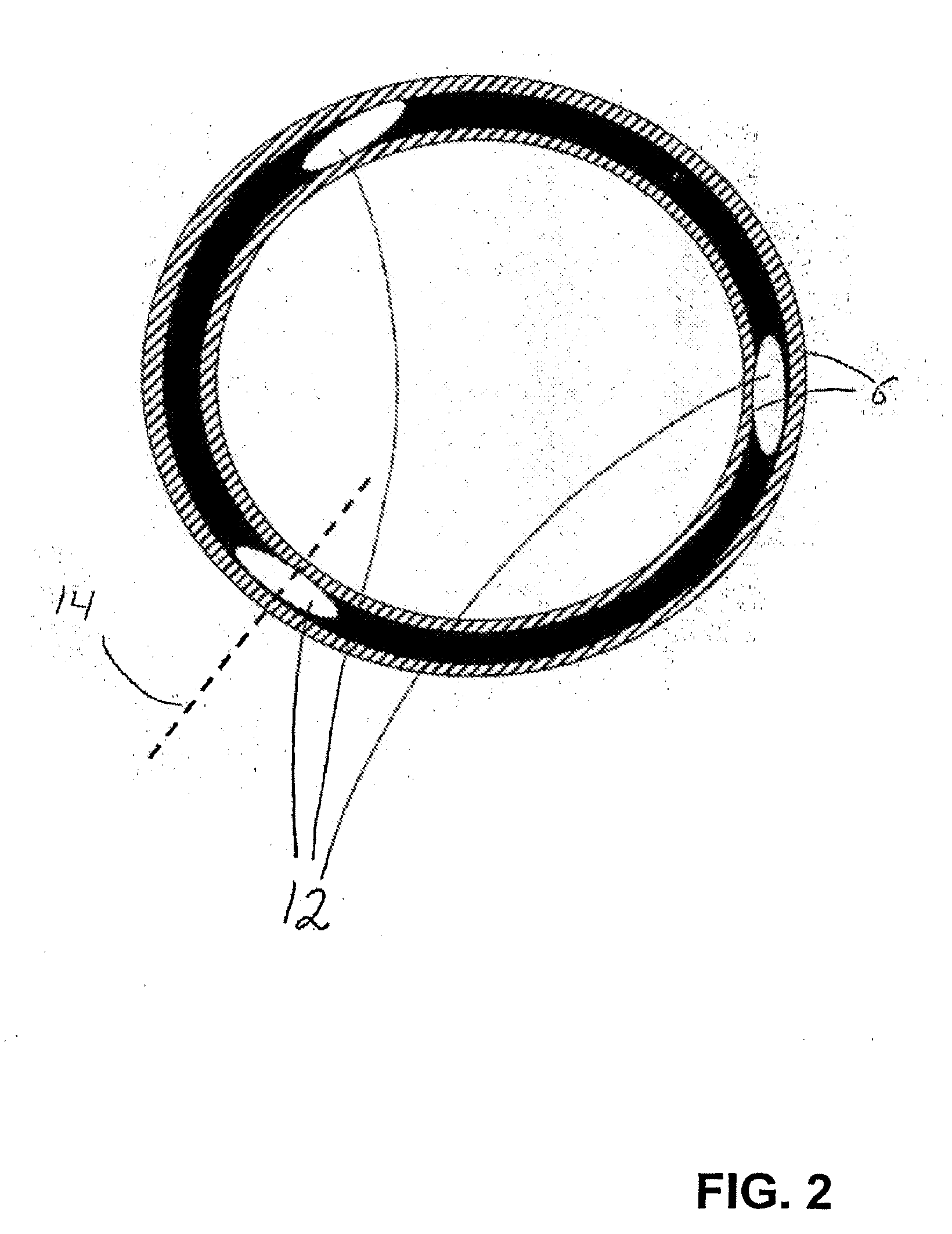
[0008]According to one embodiment, the telescopic mast according to the invention is peculiar in that the means is a rotary means interacting with an actuator which during use rotates the rotary means about an axis which is largely perpendicular to the longitudinal axis of the telescoping sections. Such an embodiment is advantageous as it enables using a rotary means which is elongated and has large contact surface, thereby enabling the provision of a continuous action on the walls in direction away from each other. It may be advantageous to use a rotary means which is slightly asymmetrical and / or in which the axis of rotation is displaced in relation to the central part of the means. Hereby is provided the possibility of positional variation of the areas on the means which are in contact with the walls. The rotary means may advantageously be covered by a friction reducing material, e.g. Teflon, in order to minimise friction and wear.
[0009]According to a second embodiment, the telescopic mast according to the invention is peculiar in that the means is a rotary member interacting with an actuator which during use rotates the rotary member about an axis which is largely parallel with the longitudinal axis of the telescoping sections. This embodiment also enables using a long rotary means having a large contact surface. A continuous action on the walls in direction away from each other may hereby be effected. It may be advantageous to use a rotary means which is slightly asymmetrical and / or in which the axis of rotation is displaced with regard to the central part of the means, as the possibility of varying the location of the areas on the means which are in contact with the walls is hereby provided. The rotary member may advantageously be covered by a friction reducing material, e.g. Teflon, in order to minimise friction between and wear of the members which are in mutual physical contact.
[0010]According to a third embodiment, the telescopic mast according to the invention is peculiar in that the means is a displacing means interacting with an actuator which during use displaces the displacing means in forward direction for pressing the walls away from each other. This embodiment enables using a play reducing member which does not have to be rotated. The displacing means may be designed as a cone or have other shapes. However, it is suitable to use a displacing means which is gradually tapered in forward direction, so that displacement in forward direction will gradually press the walls away from each other more and more. The displacing means may advantageously be covered by a friction reducing material, e.g. Teflon, in order to minimise friction between and wear of the members which are in mutual physical contact.

Problems solved by technology

None of these inventions are adequately fulfilling the requirements to stability and accuracy.

Method used


Image

  • Telescopic mast having reduced play
  • Telescopic mast having reduced play
  • Telescopic mast having reduced play

Examples


second embodiment

[0009] the telescopic mast according to the invention is peculiar in that the means is a rotary member interacting with an actuator which during use rotates the rotary member about an axis which is largely parallel with the longitudinal axis of the telescoping sections. This embodiment also enables using a long rotary means having a large contact surface. A continuous action on the walls in direction away from each other may hereby be effected. It may be advantageous to use a rotary means which is slightly asymmetrical and / or in which the axis of rotation is displaced with regard to the central part of the means, as the possibility of varying the location of the areas on the means which are in contact with the walls is hereby provided. The rotary member may advantageously be covered by a friction reducing material, e.g. Teflon, in order to minimise friction between and wear of the members which are in mutual physical contact.

third embodiment

[0010] the telescopic mast according to the invention is peculiar in that the means is a displacing means interacting with an actuator which during use displaces the displacing means in forward direction for pressing the walls away from each other. This embodiment enables using a play reducing member which does not have to be rotated. The displacing means may be designed as a cone or have other shapes. However, it is suitable to use a displacing means which is gradually tapered in forward direction, so that displacement in forward direction will gradually press the walls away from each other more and more. The displacing means may advantageously be covered by a friction reducing material, e.g. Teflon, in order to minimise friction between and wear of the members which are in mutual physical contact.

[0011]According to yet an embodiment, the telescopic mast according to the invention is peculiar in that there is used at least three rotary means and / or rotary members and / or displacing ...

first embodiment

[0016]FIG. 1 shows a cross-sectional view (in longitudinal direction of the mast) of a mast according to the invention, as seen from the front;

[0017]FIG. 2 shows a cross-sectional view (perpendicular to longitudinal direction of the mast) of a second embodiment of a mast according to the invention;

[0018]FIG. 3 shows a cross-sectional view (perpendicular to longitudinal direction of the mast) of a third embodiment of a mast according to the invention in perspective view; and


PUM


Abstract

There is disclosed a telescopic mast (2) including two or more cylindric telescoping sections (4) with parallel walls (6), where the distal one of two adjacent telescoping sections (4) is narrower than the proximal one of the two adjacent telescoping sections (4), so that the distal telescoping section (4) can be moved into and out of the proximal telescoping section (4), respectively. In the interspace (8) between two adjacent telescoping section (4) there is provided at least one means (10) interacting with an actuator (16) and pressing the adjacent walls (6) away from each other. Hereby play is eliminated or minimised.

Description

FIELD OF THE INVENTION[0001]The present invention concerns a telescopic mast including two or more cylindric telescoping sections with parallel walls, where the distal one of two adjacent telescoping sections is narrower than the proximal one of the two adjacent telescoping sections, so that the distal telescoping section can be moved into and out of the proximal telescoping section, respectively.BACKGROUND OF THE INVENTION[0002]There are many kinds of telescopic masts of which some can be extended automatically. In connection with telescoping masts, e.g. for military use, there are special requirements to stability and accuracy. U.S. Pat. No. 4,151,534 describes a free-standing mast for an antenna including a number of telescoping tubes. U.S. Pat. No. 4,137,535 describes a telescopic mast which is controlled pneumatically. The mast includes a number of telescoping tubes that may be collapsed in a base section. A piston is integrated in each section. WO 0189981 describes a telescopi...

Claims


Application Information

Patent Timeline
Patent Type & Authority Applications(United States)
IPC IPC(8): E04H12/18
CPCH01Q1/1235F16B7/14
Inventor FALCK-SCHMIDT, JAN
Owner DRS SUSTAINMENT SYST
Why Eureka
Eureka Blog
Learn More