Dynamometer

a dynamometer and braking system technology, applied in the direction of engine testing, force/torque/work measurement apparatus, structural/machine measurement, etc., can solve the problems of complicated and expensive power absorption and braking system of typical dynamometers to contain the power of the engin

Inactive Publication Date: 2010-03-04
VICKIO JR LOUIS P +2
View PDF7 Cites 44 Cited by
  • Summary
  • Abstract
  • Description
  • Claims
  • Application Information

AI Technical Summary

Benefits of technology

[0004]In the invention, the power of the engine is absorbed by accelerating the inertial flywheel, which for a piston racing engine application would weigh on the order of a ton. Since metal is inexpensive, the inventive dynamometer can be made for less than dynamometers currently on the market. The movably mounted starter motor permits the massive inertial flywheel to be used by spinning it up to a speed compatible with the speed of the engine, prior to coupling the flywheel to the engine.

Problems solved by technology

Typical dynamometers have a complicated and expensive power absorbing and braking system to contain the power of the engine and cost on the order of $100,000.

Method used


Image

  • Dynamometer
  • Dynamometer
  • Dynamometer

Examples


Embodiment Construction

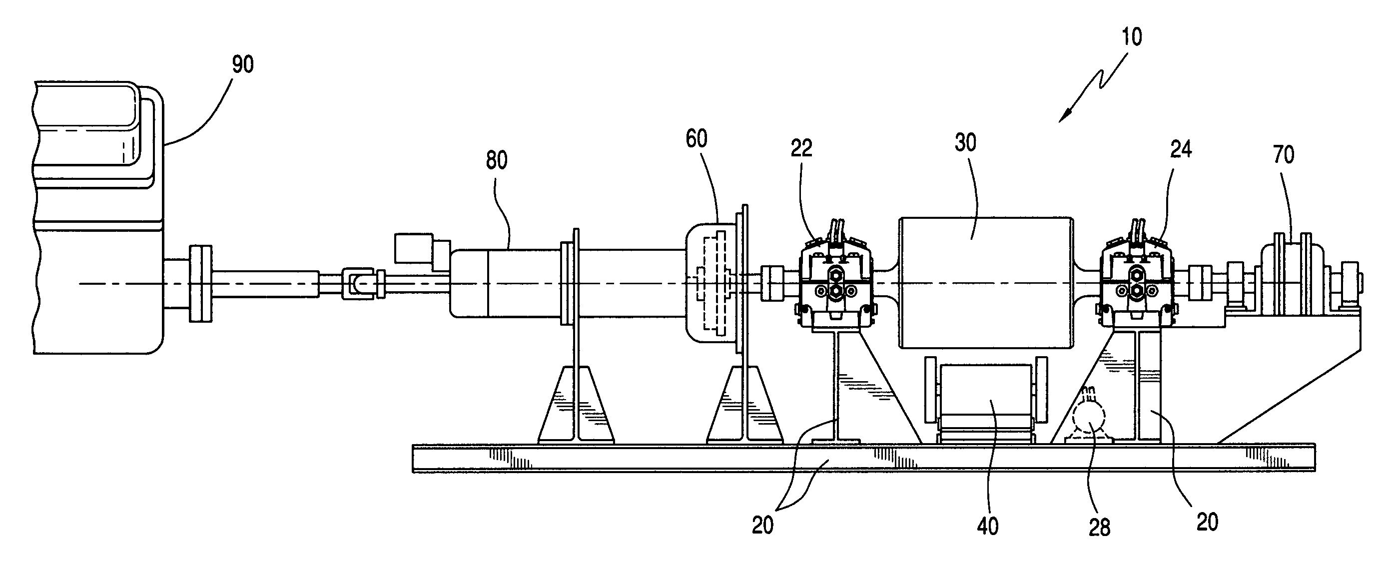
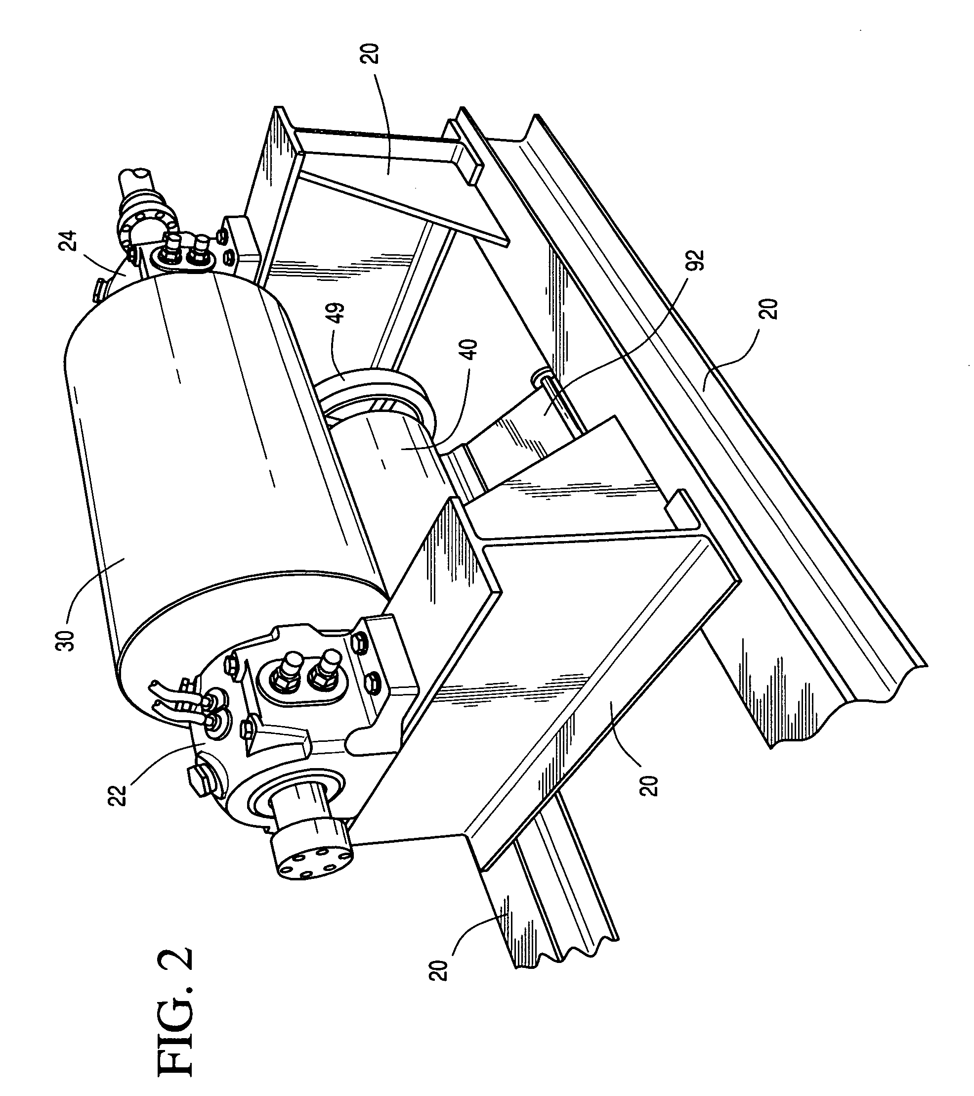
[0012]It was recognized by the inventors that use of a massive inertial flywheel, for example, a solid 2,000 pound flywheel, in a dynamometer for racing engines had promise of reducing fabrication costs. However, two problems had to be overcome. The first was starting the engine against the massive inertia of the flywheel. The second was overcoming a bearing failure problem initiated when the flywheel began to move.

[0013]The first problem was solved by using, in an exemplary embodiment, a 10-HP electric motor with two air cylinders to lift and start the rotation of the inertia flywheel by overcoming the large break-away torque--unique to this design

[0014]The second problem was solved in an exemplary embodiment by using a sleeve oil bearing instead of roller bearings to support the weight of the flywheel. The inventive system in a preferred embodiment further uses an oil circulation pump system to supply the sleeve bearings with a constant bath of oil lubrication

[0015]The inventive d...


PUM


Abstract

A dynamometer comprises a frame, an inertial flywheel, and a starter motor. The inertial flywheel is supported by the frame and the starter motor is movably mounted to the frame so as to be selectively engageable with the inertial flywheel. Means is provided for coupling an engine to be tested to the apparatus. The flywheel is brought up to speed by means of the starter motor and then coupled to the engine, which has been separately brought up to speed, via a clutch. The flywheel is supported by the frame in pressurized oil sleeve bearings.

Description

FIELD OF THE INVENTION[0001]In one aspect, the invention relates to a dynamometer for measuring a performance parameter for an internal combustion engine. In another aspect, the invention relates to a method for operating a dynamometer measuring a performance parameter for an internal combustion engine.BACKGROUND OF THE INVENTION[0002]Racing engines typically develop 750 to 1500 horsepower. They are almost always tested on a dynamometer prior to being delivered to a customer. Typical dynamometers have a complicated and expensive power absorbing and braking system to contain the power of the engine and cost on the order of $100,000. There is need for a less expensive dynamometer.SUMMARY OF THE INVENTION[0003]According to one embodiment of the invention, there is provided an apparatus comprising a frame, an inertial flywheel, and a starter motor. The inertial flywheel is supported by the frame and the starter motor is movably mounted to the frame so as to be selectively engageable wit...

Claims


Application Information

Patent Timeline
Patent Type & Authority Applications(United States)
IPC IPC(8): G01M15/00
CPCG01M15/02
Inventor VICKIO, JR., LOUIS P.VICKIO, SR., LOUIS P.VICKIO, EDWARD A.
Owner VICKIO JR LOUIS P
Why Eureka
Try Eureka