Method and device for dynamometer testing of a motor vehicle and Vehicle components
- Summary
- Abstract
- Description
- Claims
- Application Information
AI Technical Summary
Benefits of technology
Problems solved by technology
Method used
Image
Examples
Embodiment Construction
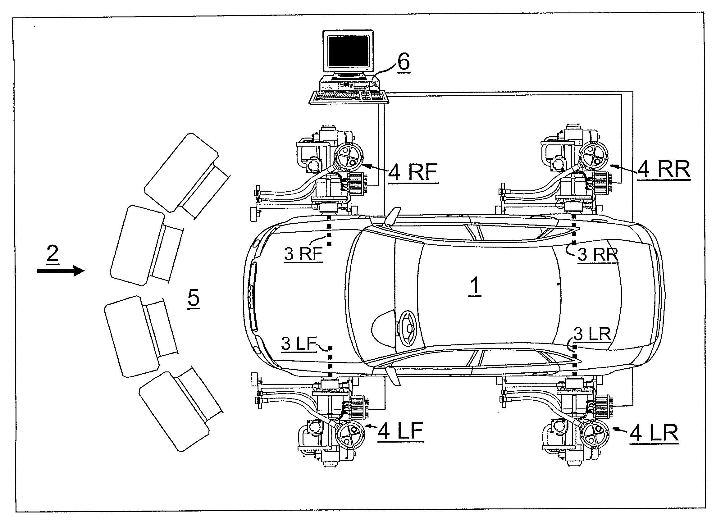
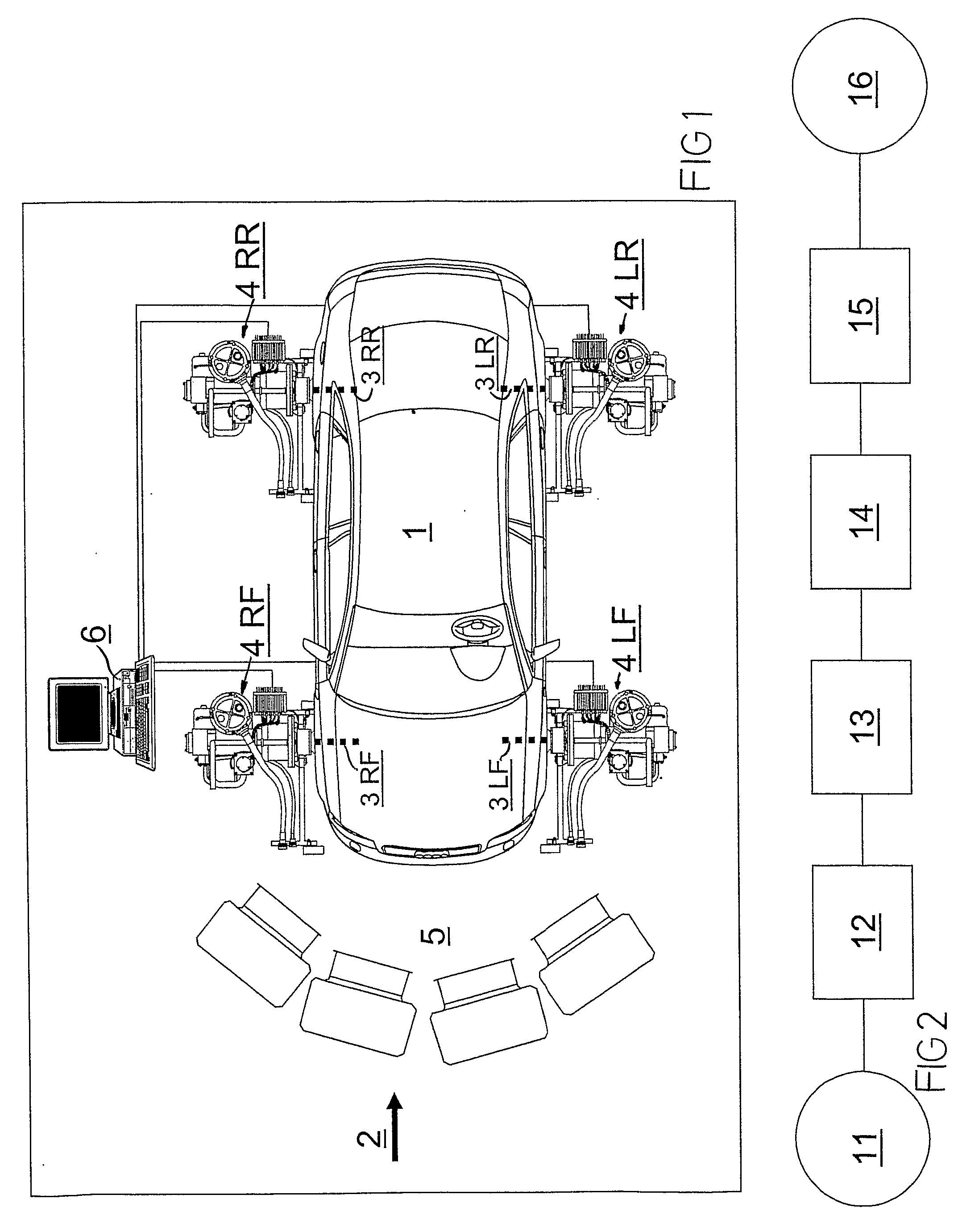
[0035]In FIG. 1, a vehicle 1 is in the process of being tested with a device according to the invention, generally indicated with 2.
[0036]Four dynamometer test units 4LF, 4RF, 4LR and 4RR are directly connected to four drive shafts of the vehicle 1 which is a four-wheel drive vehicle. The shafts are indicated with 3LF, 3RF, 3LR and 3RR. LF=left front, RF=right front, LR=left rear and RR=right rear.
[0037]Each test unit 4LF, 4RF, 4LR and 4RR includes a torque sensor (according to the background art) in order to obtain torque values during operation of the system. A rotational speed sensor (not shown) is also provided for each drive shaft.
[0038]A cooling unit 5 including a number of fans, serves to cool hydraulic fluid that has been heated because of throttling the flow during braking, by applying braking torque over the individual test units 4LF, 4RF, 4LR and 4RR. The cooling unit 5 can also be connected so as to produce a simulated air stream corresponding to the relative air movemen...
PUM
 Abstract
Description
Claims
Application Information
 - R&D
- Intellectual Property
- Life Sciences
- Materials
- Tech Scout
- Unparalleled Data Quality
- Higher Quality Content
- 60% Fewer Hallucinations
Browse by: Latest US Patents, China's latest patents, Technical Efficacy Thesaurus, Application Domain, Technology Topic, Popular Technical Reports.
© 2025 PatSnap. All rights reserved.Legal|Privacy policy|Modern Slavery Act Transparency Statement|Sitemap|About US| Contact US: help@patsnap.com


