Magnetic sensor device for and a method of sensing magnetic particles

a magnetic particle and sensor technology, applied in the direction of magnetic beads labelled molecules measurement, material magnetic variables, instruments, etc., can solve the problem of insufficient accuracy of measurement results and other problems, and achieve the effect of robust sensor readout topology

Inactive Publication Date: 2010-03-04
KONINKLIJKE PHILIPS ELECTRONICS NV
View PDF8 Cites 34 Cited by
  • Summary
  • Abstract
  • Description
  • Claims
  • Application Information

AI Technical Summary

Benefits of technology

[0011]It is an object of the invention to provide a robust sensor readout topology.

Problems solved by technology

However, sufficient accuracy of measurement results may still be problematic under undesired circumstances.

Method used


Image

  • Magnetic sensor device for and a method of sensing magnetic particles
  • Magnetic sensor device for and a method of sensing magnetic particles
  • Magnetic sensor device for and a method of sensing magnetic particles

Examples


first embodiment

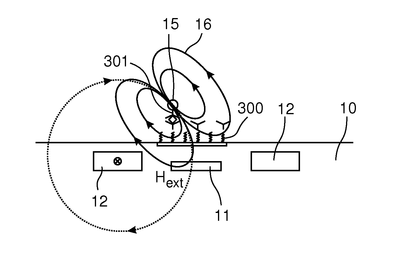
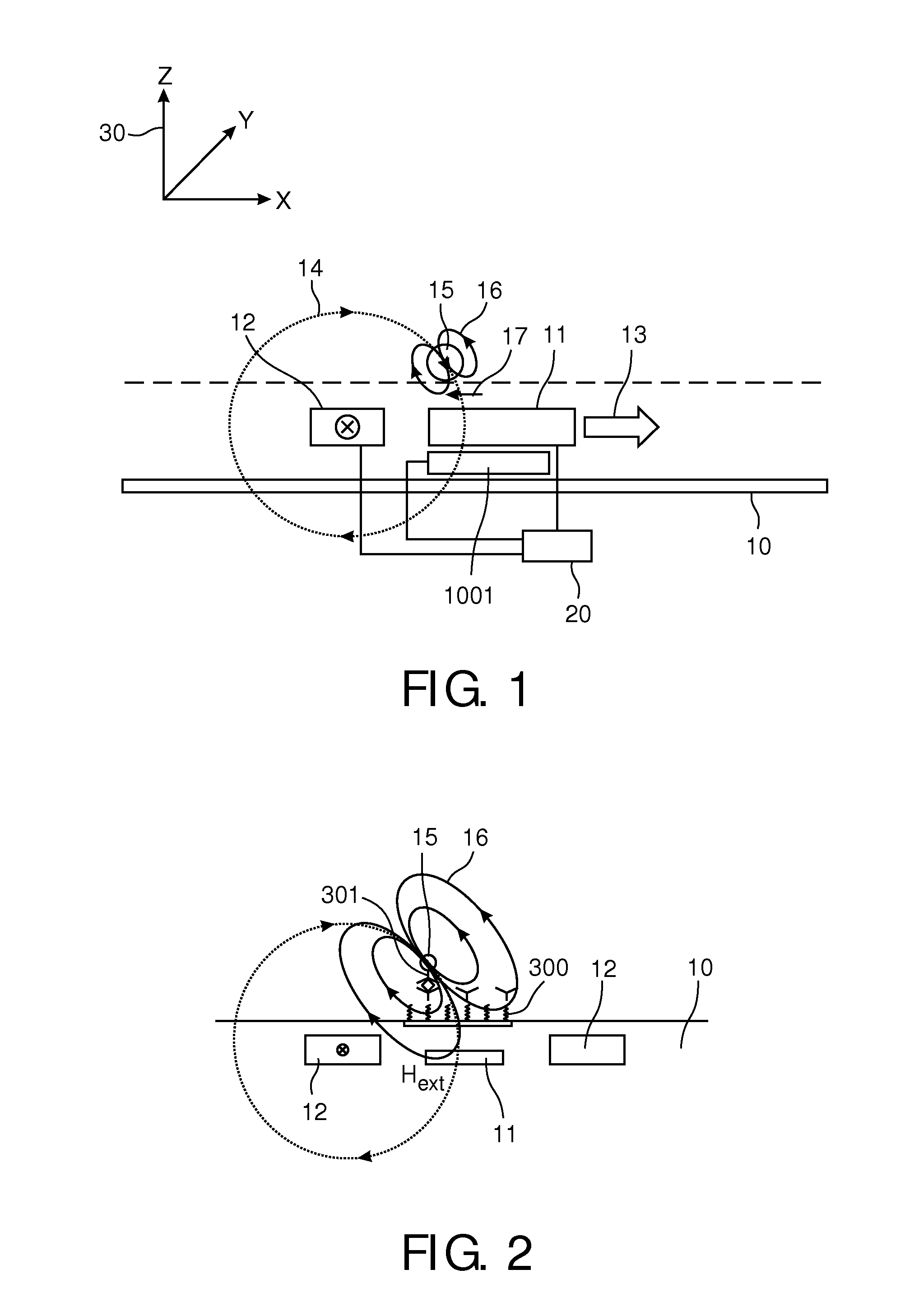
[0049]In a first embodiment the device according to the present invention is a biosensor and will be described with respect to FIG. 1. The biosensor detects magnetic particles in a sample such as a fluid, a liquid, a gas, a visco-elastic medium, a gel or a tissue sample. The magnetic particles can have small dimensions. With nano-particles are meant particles having at least one dimension ranging between 0.1 nm and 1000 nm. The magnetic particles can acquire a magnetic moment due to an applied magnetic field.

[0050]The device may comprise a substrate 10 and a circuit e. g. an integrated circuit.

[0051]A measurement surface of the device is represented by the dotted line in FIG. 1. The circuit may comprise a magneto-resistive sensor 11 as a sensor element and a first magnetic field generator in the form of a conductor 12. The terms sensor unit 11, sensor, and sensor device are used as synonyms in the following. The sensor unit 11 can be any suitable sensor unit 11 based on the detectio...

embodiment 1100

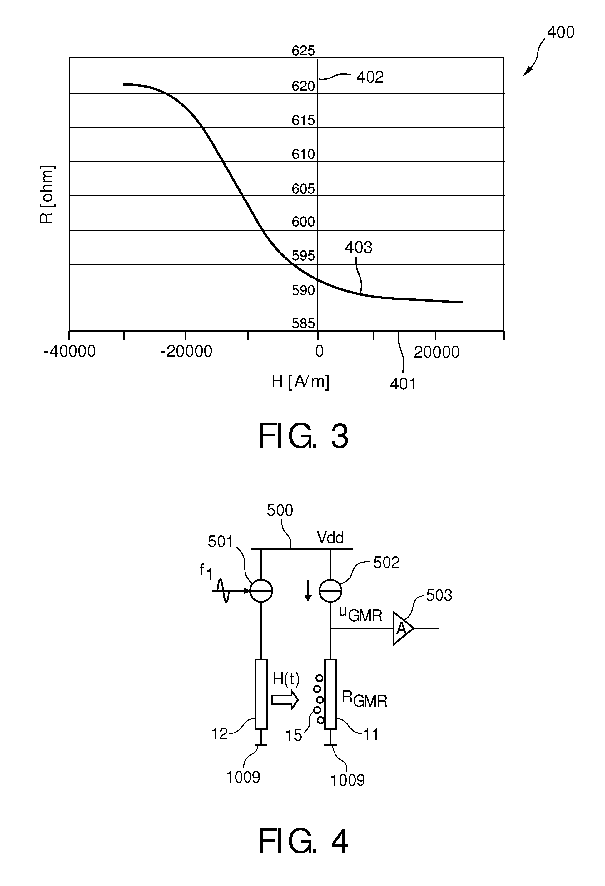
[0096]In the embodiment 1100 of FIG. 10, a first chopper 1101 is additionally connected between the sensing unit 11 and the loop filter 1006, and a second chopper 1102 is connected between the analog to digital converter 1004 and the digital to analog converter 1005. An amplifier 1103 is connected between the current source 1008 and the chopper 1101.

[0097]This feedback-wire 1001 (or reference-wire) should be placed in such a way that its magnetic field has a strong component directly in the sensitive plane of the GMR 11, while on the other side exciting the beads 15 as little as possible. The electrical output signal of the GMR 11 will represent the sum of the magnetic field from the feedback wire 12 and the magnetic field induced by the beads 15, and is fed to the input of loop filter H 1006. Due to the negative feedback in the converter, the average sum signal on the GMR 11 will be regulated towards zero. In other words, the magnetic feedback field has averagely cancelled the magn...


PUM


Abstract

A magnetic sensor device (1000) for sensing magnetic particles (15), the magnetic sensor device (1000) comprising a first magnetic field generator unit (12) excitable for generating a first magnetic field, a sensing unit (11) adapted for sensing a signal indicative of the presence of the magnetic particles (15) in the first magnetic field, a second magnetic field generator unit (1001) adapted for generating a second magnetic field affecting the sensing unit (11), and a processing circuitry (1002) adapted for processing the signal to form a digitized signal and adapted for feeding back the processed signal to the second magnetic field generator unit (1001).

Description

FIELD OF THE INVENTION[0001]The invention relates to a magnetic sensor device for sensing magnetic particles.[0002]The invention further relates to a method of sensing magnetic particles.BACKGROUND OF THE INVENTION[0003]A biosensor may be a device for the detection of an analyte that combines a biological component with a physicochemical or physical detector component.[0004]Magnetic biosensors may use the Giant Magnetoresistance Effect (GMR) for detecting biological molecules being magnetic or being labeled with magnetic beads.[0005]In the following, biosensors will be explained which may use the Giant Magnetoresistance Effect.[0006]WO 2005 / 010542 discloses the detection or determination of the presence of magnetic particles using an integrated or on-chip magnetic sensor element. The device may be used for magnetic detection of binding of biological molecules on a micro-array or biochip. Particularly, WO 2005 / 010542 discloses a magnetic sensor device for determining the presence of ...

Claims


Application Information

Patent Timeline
Patent Type & Authority Applications(United States)
IPC IPC(8): G01R33/12
CPCB82Y25/00G01R33/07G01R33/1269G01R33/12G01R33/093
Inventor VAN DEN HOMBERG, JOHANNES A.T.M.TOL, JEROEN J.A.DURIC, HARIS
Owner KONINKLIJKE PHILIPS ELECTRONICS NV
Why Eureka
Try Eureka