Camera module and electronic device including the same

Inactive Publication Date: 2010-03-04
SHARP KK
View PDF12 Cites 26 Cited by
  • Summary
  • Abstract
  • Description
  • Claims
  • Application Information

AI Technical Summary

Benefits of technology

[0028]The present invention is accomplished in view of the problem, and its object is to provide a camera module and an electronic device which can prevent generation of

Problems solved by technology

This will adversely affect the opening and closing of the light path which

Method used


Image

  • Camera module and electronic device including the same
  • Camera module and electronic device including the same
  • Camera module and electronic device including the same

Examples


Embodiment Construction

[0062]An embodiment of the present invention is described below with reference to the attached drawings.

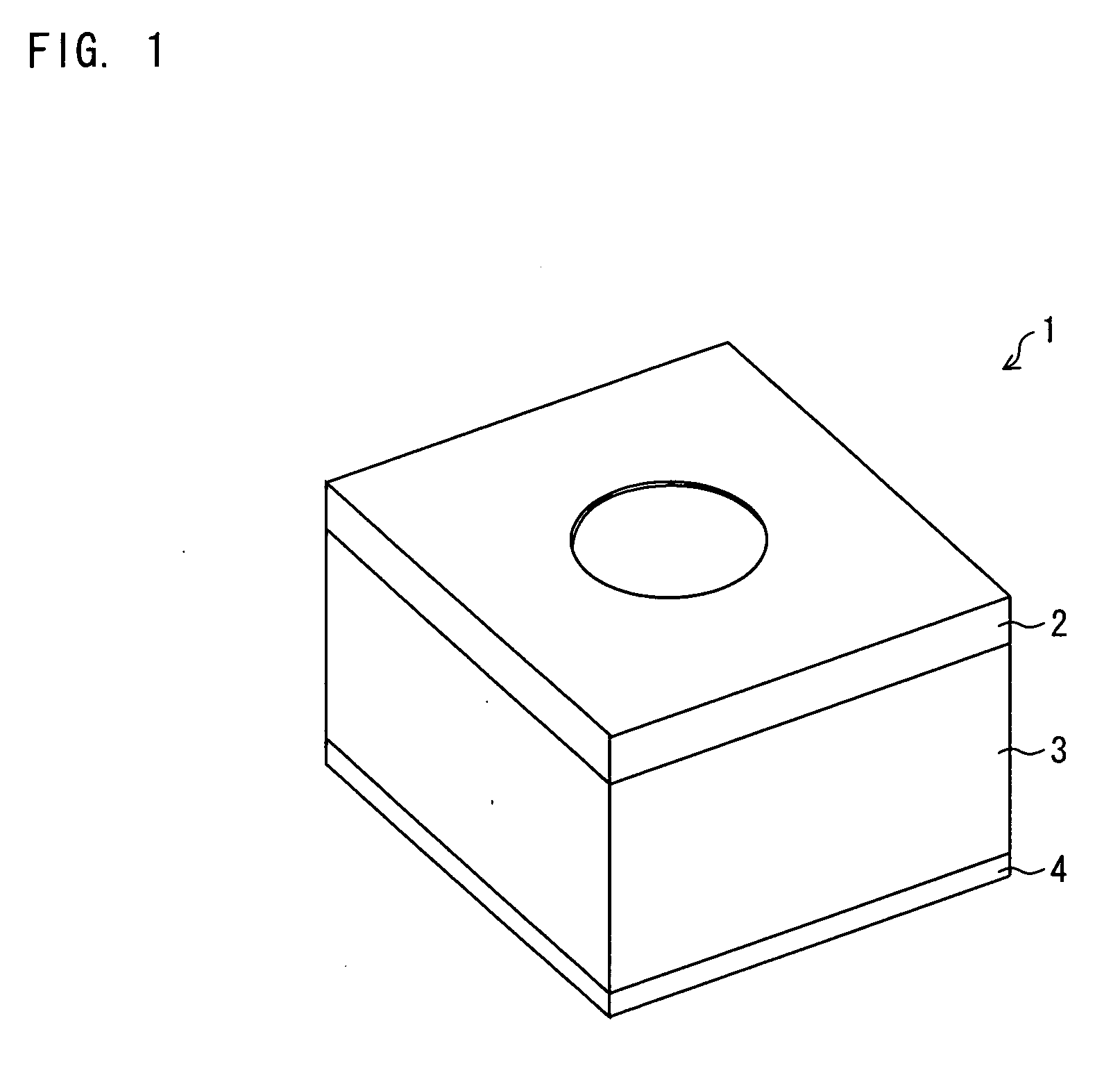
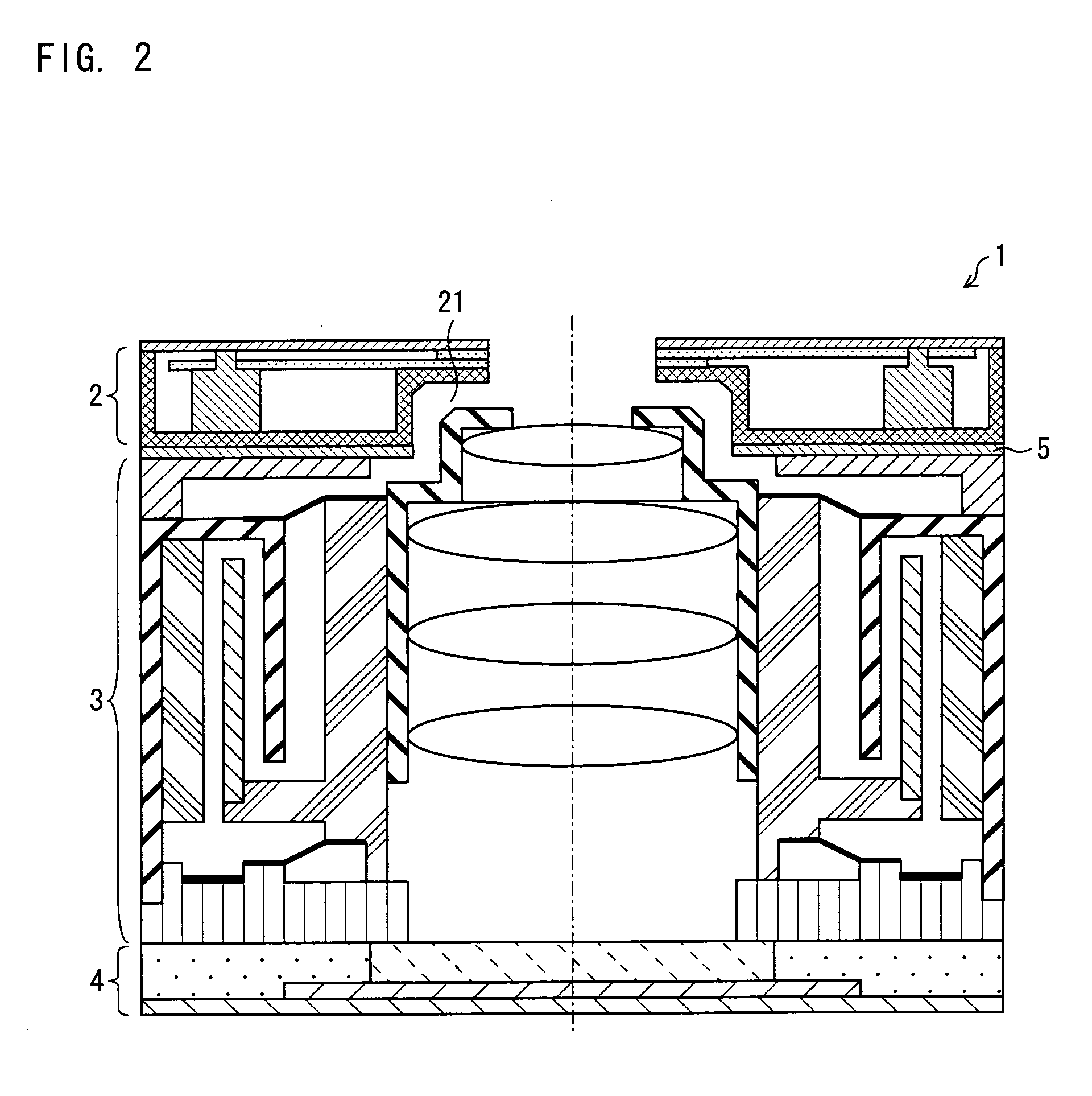
[0063]FIG. 1 is a perspective view illustrating a camera module including a lens drive device of the present invention. FIG. 2 is a cross-sectional view of the camera module including the lens drive device of the present invention.

[0064]As shown in FIG. 1, a camera module 1 of the present embodiment has a three-layer structure in which a mechanical shutter (shutter section) 2, a lens unit (lens drive section) 3, and an image pickup unit 4 are staked in this order in an optical axis direction. In the camera module 1 of the present embodiment, a magnetic shielding plate 5 is provided between the mechanical shutter 2 and the lens unit 3 (see FIG. 2). For convenience, in the following description, a side on which the mechanical shutter 2 is provided is referred to as “upward”, whereas a side on which the image pickup unit 4 is provided is referred to as “downward”.

2>

[0065]FIG. 3 is a ...


PUM


Abstract

A camera module 1 of the present invention includes a moving magnet type mechanical shutter 2 and a lens unit 3 (lens drive section) for driving a lens by electromagnetic force. A magnetic field for driving the lens is set so that a light path is closed by a shutter fin while a magnetic field leaked from the lens unit 3 is acting on a drive mechanism of the mechanical shutter 2. With the configuration, the leak magnetic field leaked from the lens unit 3 causes the light path to be closed at a faster speed by the shutter fin of the mechanical shutter 2. Accordingly, generation of a smear can be prevented by the camera module including the lens drive section and the moving magnet type mechanical shutter, which are driven by the electromagnetic force.

Description

[0001]This Nonprovisional application claims priority under 35 U.S.C. §119(a) on (i) Patent Application No. 2008-220246 filed in Japan on Aug. 28, 2008 and (ii) Patent Application No. 2009-180498 filed in Japan on Aug. 3, 2009, the entire contents of which are hereby incorporated by reference.TECHNICAL FIELD[0002]The present invention relates to: a camera module which is provided in an electronic device such as a mobile phone; and an electronic device including the camera module. More specifically, the present invention relates to: a camera module which (i) includes a moving magnet type mechanical shutter and an electromagnetic driven type (VCM type) lens drive section and (ii) addresses a smear phenomenon; and an electronic device including the camera module.BACKGROUND ART[0003]For example, a phenomenon called “smear” occurs in a camera module including a CCD (Charge Coupled Device) as an image pickup element. The smear is a phenomenon in which a photographed image has a white zona...

Claims


Application Information

Patent Timeline
IPC IPC(8): G03B13/32H04N5/225G03B9/08
CPCG03B9/08H04N5/23212H04N5/2257H04N5/2251H04N23/52H04N23/57H04N23/55
Inventor SEKIMOTO, YOSHIHIROSEMI, ATSUSHI
Owner SHARP KK
Why Eureka
Try Eureka