Detection of open scanner lid

a scanner lid and lid technology, applied in the field of detection of open scanner lids, can solve the problems of unreliable lid opening detection and unresponsive apparatus at firs

Inactive Publication Date: 2010-03-04
EASTMAN KODAK CO
View PDF12 Cites 30 Cited by
  • Summary
  • Abstract
  • Description
  • Claims
  • Application Information

AI Technical Summary

Problems solved by technology

If a user were to push the start button during or soon after the apparatus is in the sleep mode, the apparatus may seem unresponsive a

Method used


Image

  • Detection of open scanner lid
  • Detection of open scanner lid
  • Detection of open scanner lid

Examples


Embodiment Construction

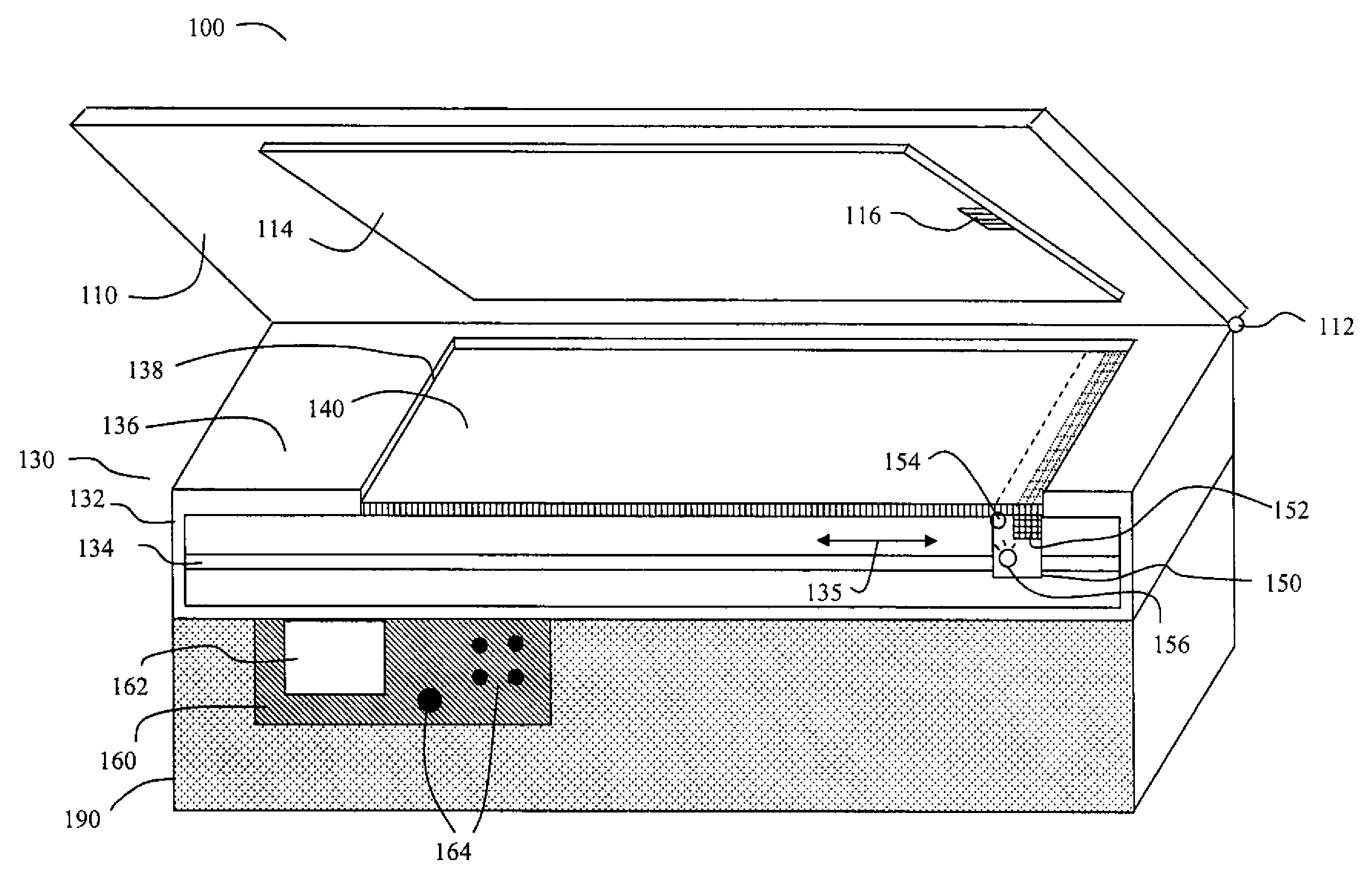
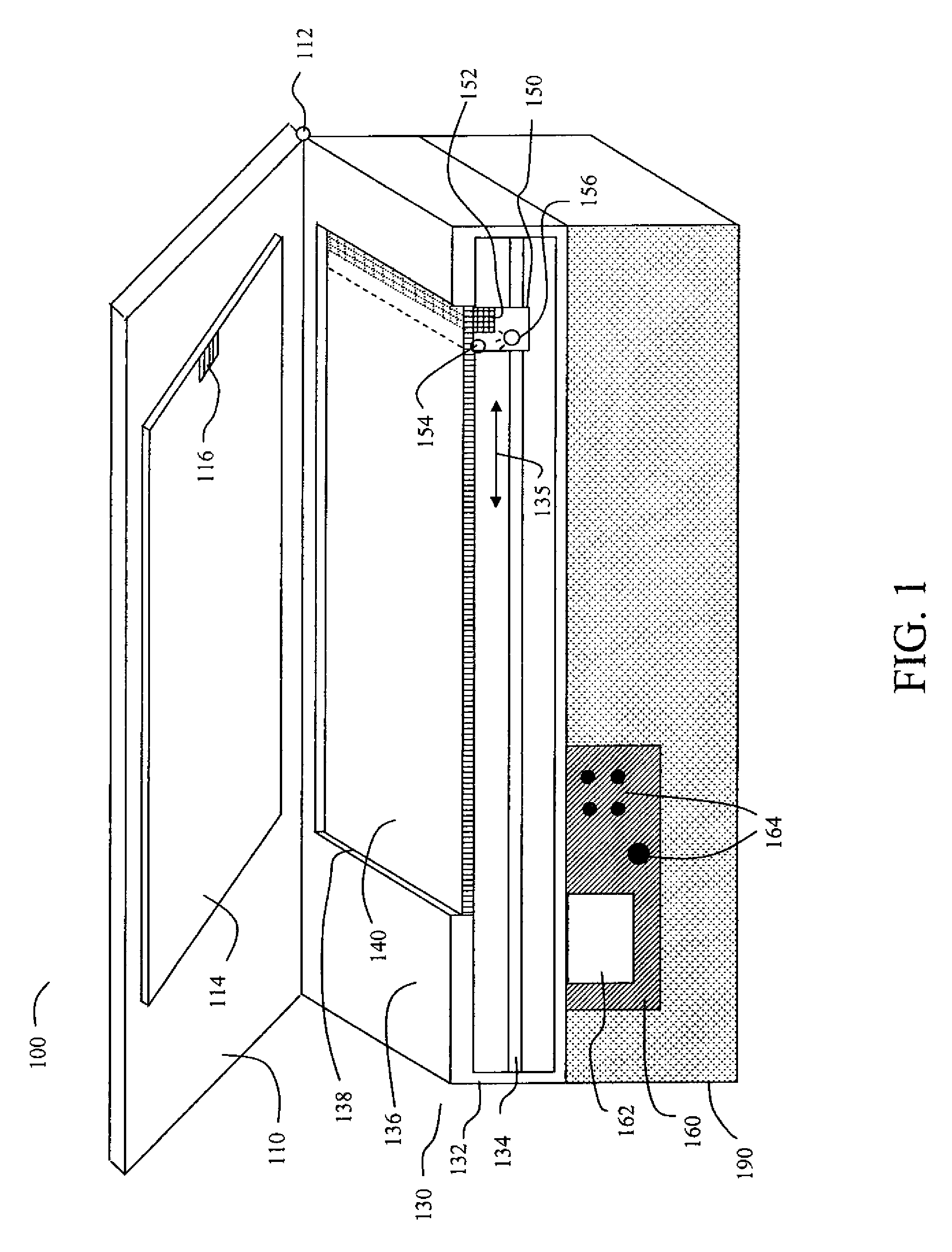
[0025]FIG. 1 shows a perspective view of a multifunction printer 100 including a scanning apparatus 130 and a printing apparatus 190. In this view, the front portion of scanning apparatus 130 is cut away in order to show internal features of the scanning apparatus more clearly. Multifunction printer 100 can do printing, scanning of documents, or copying of documents (e.g., printing plus scanning). The printing apparatus 190 portion of the multifunction printer 100 is not central to the invention, and other embodiments of the invention include a separate scanning apparatus, which would be similar to multifunction printer 100 without the printing apparatus 190.

[0026]Control panel 160 for the apparatus is shown in FIG. 1 as being mounted on the front of printing apparatus 190, but this was done partly for illustrative purposes so as not to obscure features of the scanning apparatus 130. In other embodiments and especially for a separate scanning apparatus (not shown) where there is no ...


PUM


Abstract

A scanning apparatus for scanning an image that includes a transparent plate and a target region having a predetermined optical reflectance. Also included is a movable sensor array, having a home position that is in optical communication with the target region when a lid of the scanning apparatus is closed. A light source illuminates the target region, and a controller analyzes a signal sent from the movable sensor array and subsequently initiating at least one function for the scanning apparatus.

Description

FIELD OF THE INVENTION[0001]The present invention relates to the detection of the open or closed status of a lid on a scanning apparatus. The scanning apparatus can be either a stand-alone device or a part of a copier, or a multifunction printerBACKGROUND OF THE INVENTION[0002]Optical scanners operate by imaging an object (e.g., a document) with a light source and sensing a resultant light signal with an optical sensor array. Each optical sensor or photoreceptor in the array generates a data signal representative of the intensity of light impinged thereon for a corresponding portion of the imaged object. The data signals from the array sensors are then processed (typically digitized) and stored in a temporary memory such as a semiconductor memory or on a hard disk of a computer; for example, for subsequent manipulation and printing or display, such as on a computer monitor. The image of the scanned object is projected onto the optical photo sensor array incrementally by use of a mov...

Claims


Application Information

Patent Timeline
IPC IPC(8): H04N1/04
CPCH04N1/00018H04N1/00087H04N2201/0422H04N1/1017H04N1/00551
Inventor JASINSKI, DAVID WAYNEFARNUNG, KIRK DOUGLAS
Owner EASTMAN KODAK CO
Why Eureka
Try Eureka