Device for mixing light of side emitting leds

a technology of side-emitting leds and mixing devices, which is applied in semiconductor devices for light sources, point-like light sources, lighting and heating apparatus, etc., can solve the problems of limited lighting system distance between leds, affecting the effect of color mixing, and reducing the amount of leds, so as to achieve good color mixing properties

Inactive Publication Date: 2010-03-04
KONINKLIJKE PHILIPS ELECTRONICS NV
View PDF8 Cites 1 Cited by
  • Summary
  • Abstract
  • Description
  • Claims
  • Application Information

AI Technical Summary

Benefits of technology

[0009]It is an object of the present invention to at least partly overcome the problems of the prior art and to pro...

Problems solved by technology

The distance between the LEDs presents a limitation to such a lighting system, because the intensity should remain at an essentially constant level along the direction of the row.
Hence, in order to maintain the constant luminance level, it is not possible to reduce the amount of LEDs by increasing the distance between them without...

Method used


Image

  • Device for mixing light of side emitting leds
  • Device for mixing light of side emitting leds
  • Device for mixing light of side emitting leds

Examples


Embodiment Construction

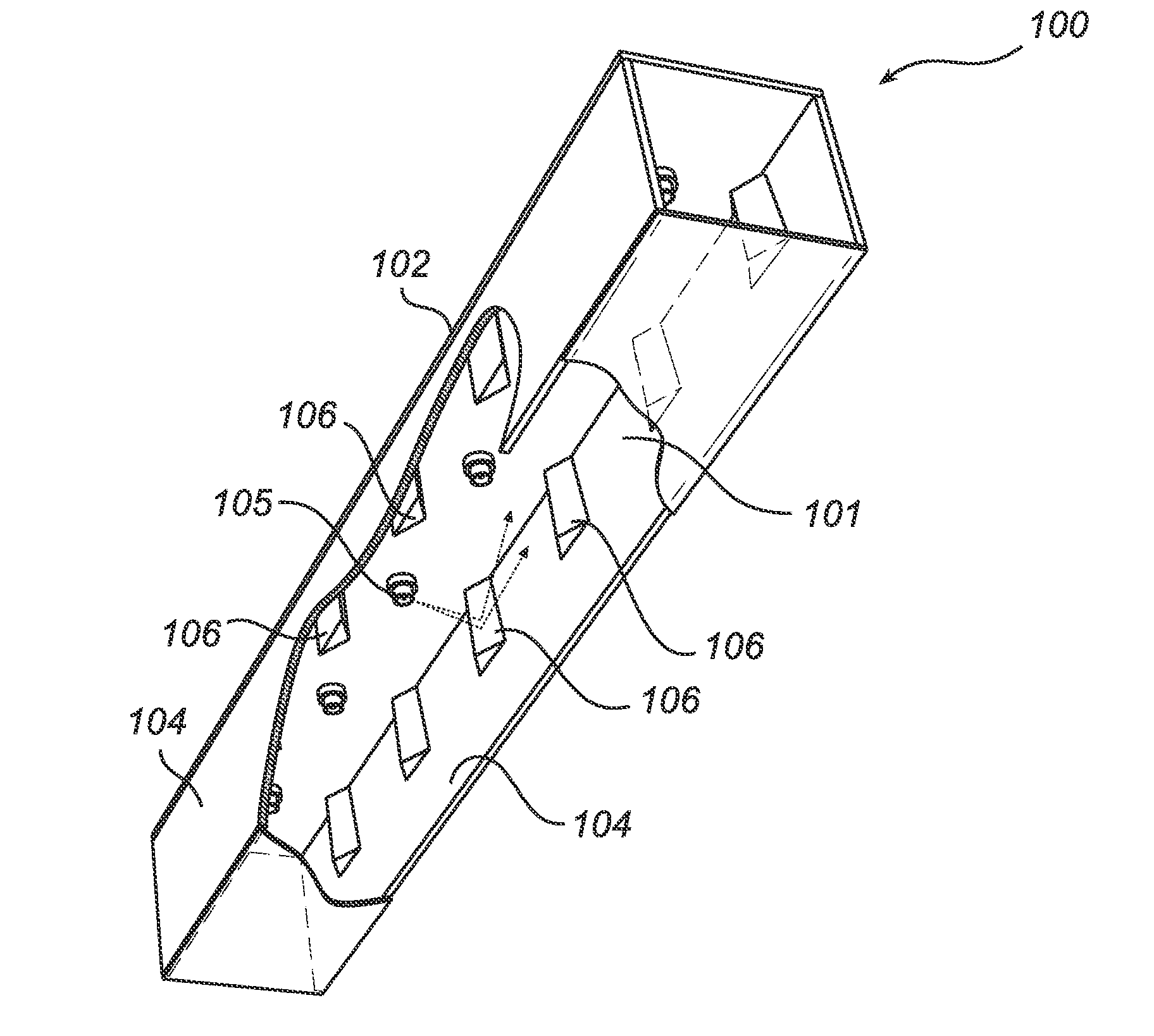
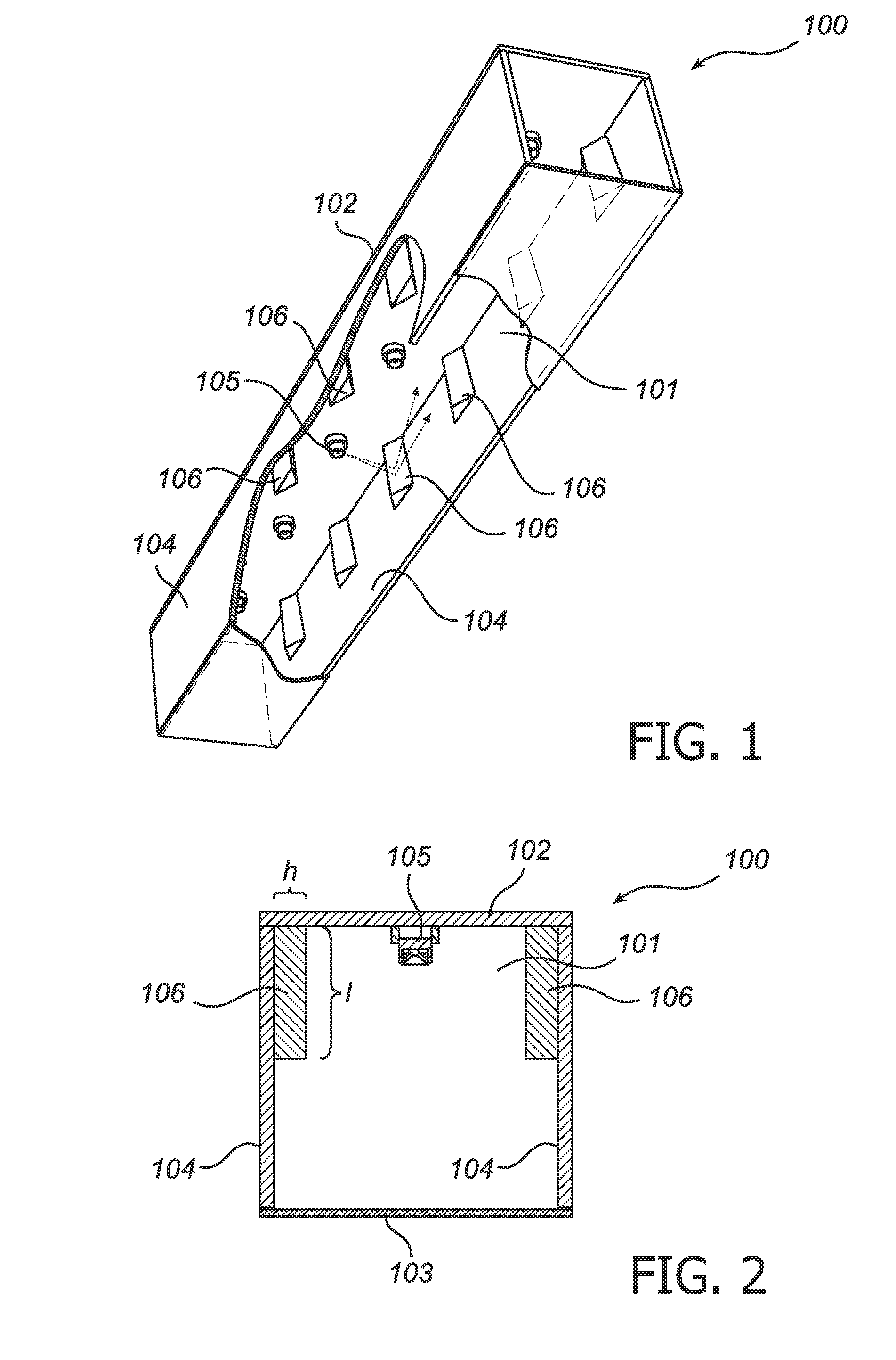
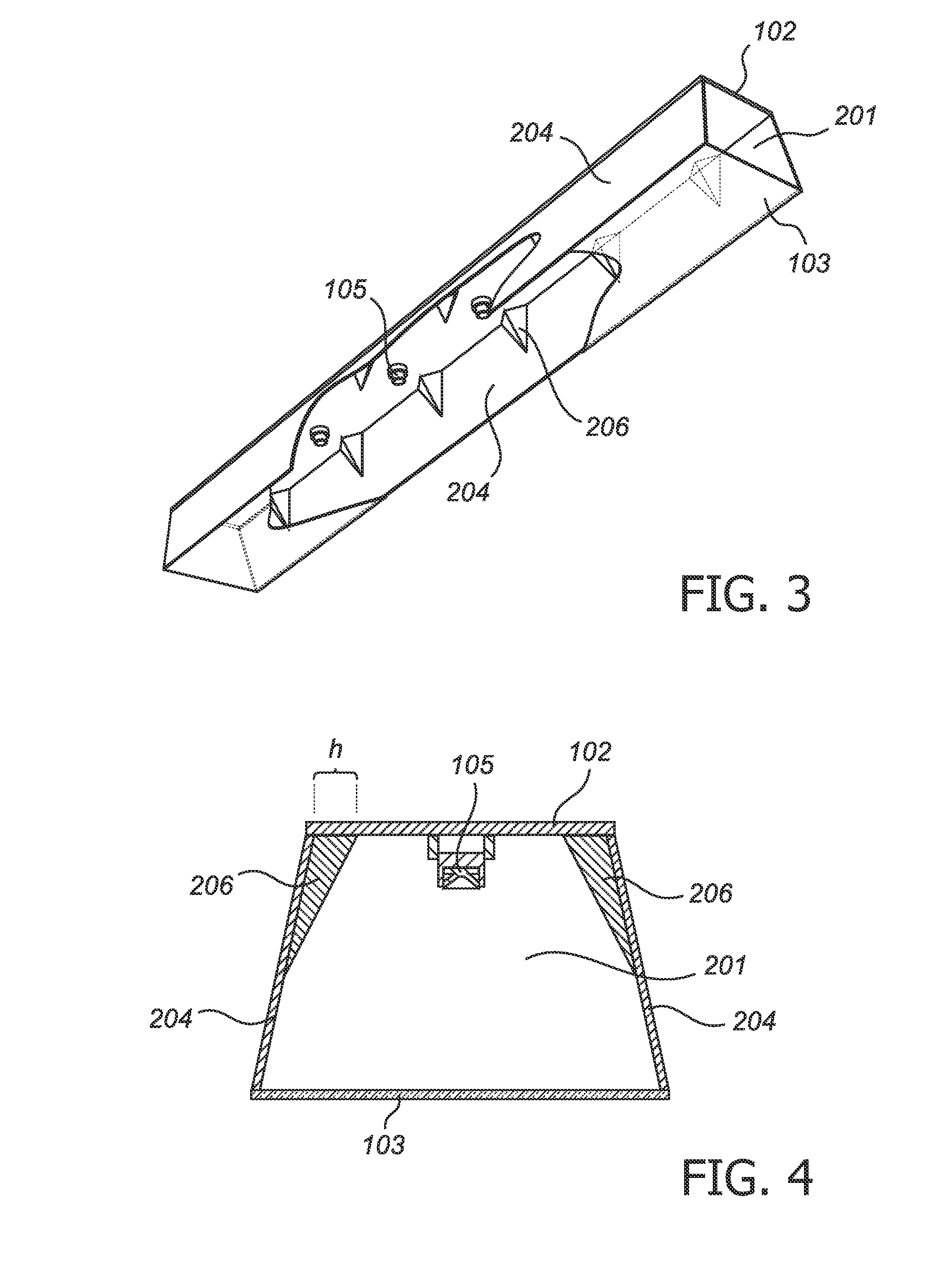
[0032]An exemplary embodiment of a light-emitting device 100 according to the present invention is illustrated in FIGS. 1 and 2, and comprises a housing 101 and an array of light emitting diodes 105 arranged in a row.

[0033]The housing 101 is longitudinally extended and comprises a top wall 102, an opposing diffusing surface 103, and two mutually opposing elongated sidewalls 104 that connects the top surface and the diffusing surface.

[0034]The housing 101 it self represents a separately contemplated aspect of the present invention, even though it in the following description is described as a component of a light emitting device.

[0035]The array of mutually spaced apart LEDs 105 is arranged on the top surface, along the longitudinal extension of the housing, facing the diffusing surface 103 (i.e. inside the housing).

[0036]The top wall 102 is longitudinally elongated along with the housing. The inside surface of the top wall 102, i.e. the surface that faces the diffusing surface 103 is...


PUM


Abstract

A light emitting device (100) is provided that comprises a longitudinally elongated housing (101) comprising a top wall (102) and opposing diffusing surface (103), and two mutually opposing reflective longitudinally elongated sidewalls (104) connecting said top wall (102) with said diffusing surface (103). An array of mutually spaced apart light emitting diodes (105) arranged is in said housing along the longitudinal extension thereof, and at least one of said sidewalls (104) is provided with an array of mutually spaced apart light redirecting means (106). The light redirecting means reflect light away from the LED that emitted the light, leading to a good mixing of light from the LEDs in the array.

Description

FIELD OF THE INVENTION[0001]The present invention relates to a light emitting device that comprises a longitudinally elongated housing, comprising a top wall and an opposing diffusing surface, and two mutually opposing reflective longitudinally elongated sidewalls connecting said top wall with said diffusing surface, and an array of mutually spaced apart light emitting diodes arranged in said housing along the longitudinal extension thereof. The present invention also relates to such a housing it self.BACKGROUND OF THE INVENTION[0002]Color mixing for indoor lighting has become more and more important the last years. Using LED's for color mixing can make it possible to have more extreme color variations in a smaller volume.[0003]Color mixing of a row of LEDs may for example be done by mixing light from the LEDs on an optical diffuser. The distance between the LEDs presents a limitation to such a lighting system, because the intensity should remain at an essentially constant level alo...

Claims


Application Information

Patent Timeline
IPC IPC(8): F21V9/00F21V1/00
CPCF21V7/00F21Y2103/003F21Y2101/02F21V15/01F21Y2103/10F21Y2115/10
Inventor KOSTERS, PAULUS GERARDUS HENRICUSWAUMANS, LARS RENE CHRISTIAN
Owner KONINKLIJKE PHILIPS ELECTRONICS NV
Why Eureka
Try Eureka