Liquid-crystal display panel and liquid-crystal display device

A liquid crystal display panel and liquid crystal layer technology, which is applied in nonlinear optics, instruments, optics, etc., can solve the problems of poor color display effect and poor color display effect of liquid crystal display panel, so as to improve the color display effect and color mixing effect. Good, large color mixing area effect

Inactive Publication Date: 2007-04-04
INNOCOM TECH SHENZHEN +1
View PDF0 Cites 3 Cited by
  • Summary
  • Abstract
  • Description
  • Claims
  • Application Information

AI Technical Summary

Problems solved by technology

[0006] In order to overcome the problem of poor color display effect of the prior art liquid crystal display panel, it is necessary to provide a liquid crystal display panel with good color display effect
[

Method used


Image

  • Liquid-crystal display panel and liquid-crystal display device
  • Liquid-crystal display panel and liquid-crystal display device
  • Liquid-crystal display panel and liquid-crystal display device

Examples


Embodiment Construction

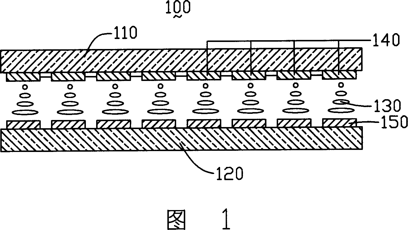
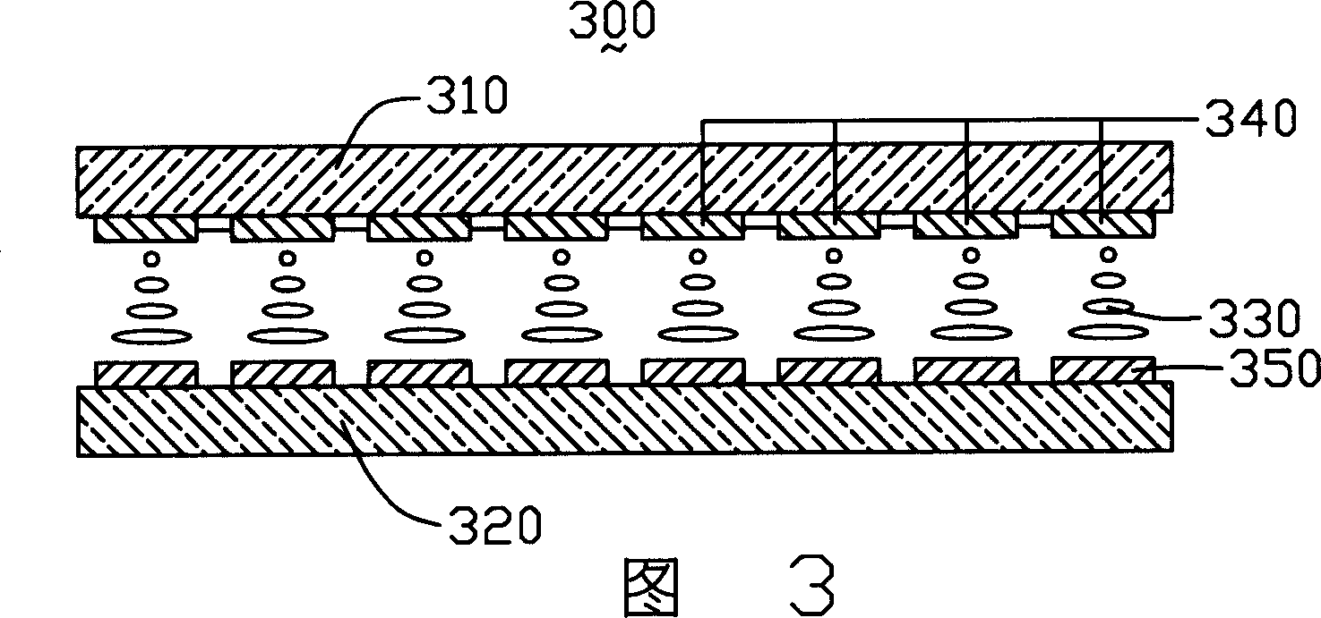
[0024] Please refer to FIG. 3 , which is a schematic structural diagram of the first embodiment of the liquid crystal display panel of the present invention. The liquid crystal display panel 300 includes a first substrate 310 , a second substrate 320 , a liquid crystal layer 330 , a plurality of color filter units 340 and a plurality of pixel electrodes 350 . The liquid crystal layer 330 is located between the first substrate 310 and the second substrate 320, the color filter unit 340 is disposed on the inner surface of the first substrate 310, the pixel electrode 350 is disposed on the inner surface of the second substrate 320, the color filter unit Both the unit 340 and the pixel electrode 350 have a zigzag structure.

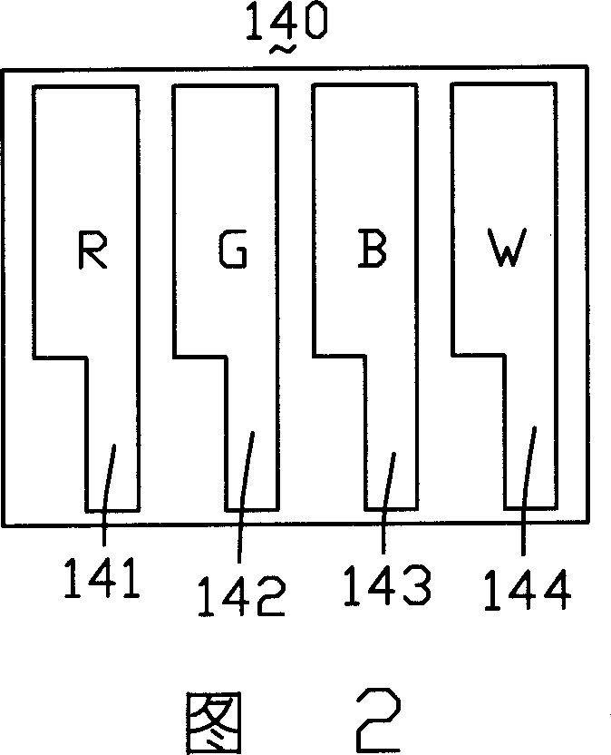
[0025] Please refer to Fig. 4, the color filter unit 340 includes four sub-filter units, which are red (R) color sub-filter unit 341, green (G) color sub-filter unit 342, blue (B) color sub-filter unit The light unit 343 and the white (W) color sub-filter un...


PUM


Abstract

A liquid crystal display face plate consists of the first base plate, the second base plate and liquid crystal layer sandwiched between the first and the second base plates. It is featured as setting multiple color filtering unit at internal surface of a base plate and forming each color filtering unit by four color filtering subunits of red color filtering subunit, green color filtering subunit, blue color filtering subunit and white color filtering subunit; and setting said color filtering unit to be structure in zigzag form.

Description

【Technical field】 [0001] The invention relates to a liquid crystal display panel and a liquid crystal display device using the liquid crystal display panel. 【Background technique】 [0002] Liquid crystal display devices have the characteristics of thinness, low power consumption and less radiation. They are widely used in computer monitors, LCD TVs, mobile phones and portable computers, and become the mainstream of displays. However, higher requirements are placed on display brightness and color display effects. . [0003] Generally speaking, a liquid crystal display device uses three primary colors of red (R), green (G), and blue (B) to display color images. Since the liquid crystal itself does not emit light, the backlight module needs to provide a light source. However, the brightness of the light source provided by the backlight module is limited, and the light loss of the optical film layers such as polarizers and color filters of the liquid crystal display device is s...

Claims


Application Information

Patent Timeline
IPC IPC(8): G02F1/1335
Inventor 杨秋莲
Owner INNOCOM TECH SHENZHEN
Why Eureka
Try Eureka