Vertical axis wind turbine

a wind turbine and vertical axis technology, applied in the direction of rotors, renewable energy generation, greenhouse gas reduction, etc., can solve the problems of local resistance to their installation, difficulty in installation and maintenance, and decrease in the availability of fuels typically used

Inactive Publication Date: 2010-03-04
SNEERINGER CHARLES P
View PDF8 Cites 34 Cited by
  • Summary
  • Abstract
  • Description
  • Claims
  • Application Information

AI Technical Summary

Benefits of technology

[0011]Preferably, the one or more blades are coupled to the arms at a neutral point of the blade such that the blade may freely rotate to assume an angle of attack associated with the desired lift-to-drag ratio of the blade.

Problems solved by technology

With the increasing costs and decreasing availability of fuels typically used to produce power, wind turbines are being implemented in greater numbers.
HAWTs have received great success; however, they suffer from a number of drawbacks.
Therefore, their height makes them difficult to install and maintain and makes them visible from great distances, which often causes local resistance to their installation.
Typically, the blades are very large and thus, repositioning the blade orientation can require a significant amount of energy.
Furthermore, HAWTs can often suffer from structural failure caused by turbulence because the blades are generally installed upstream from the tower.
One drawback to the use of VAWTs in the past is that the drag created when the blades rotate into the wind can be excessive and thus, reduce the power output of the turbine.
Although this reliance on drag may produce a higher torque, it lowers the power output by making the shaft rotate at a speed that is less than or equal to the wind speed.

Method used


Image

  • Vertical axis wind turbine
  • Vertical axis wind turbine
  • Vertical axis wind turbine

Examples


Embodiment Construction

[0027]FIGS. 1-7 and the following description depict specific examples to teach those skilled in the art how to make and use the best mode of the invention. For the purpose of teaching inventive principles, some conventional aspects have been simplified or omitted. Those skilled in the art will appreciate variations from these examples that fall within the scope of the invention. Those skilled in the art will appreciate that the features described below can be combined in various ways to form multiple variations of the invention. As a result, the invention is not limited to the specific examples described below, but only by the claims and their equivalents.

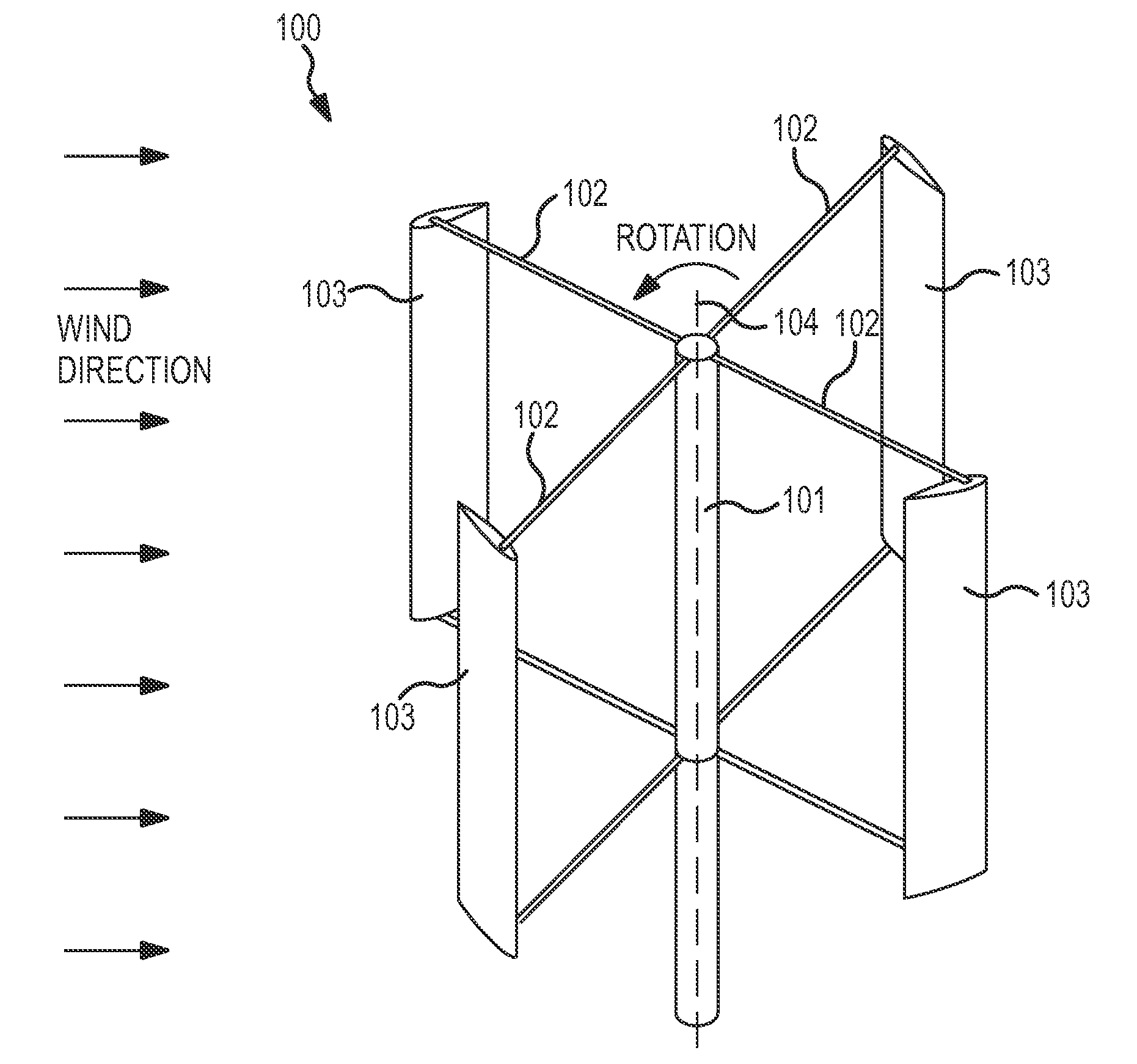
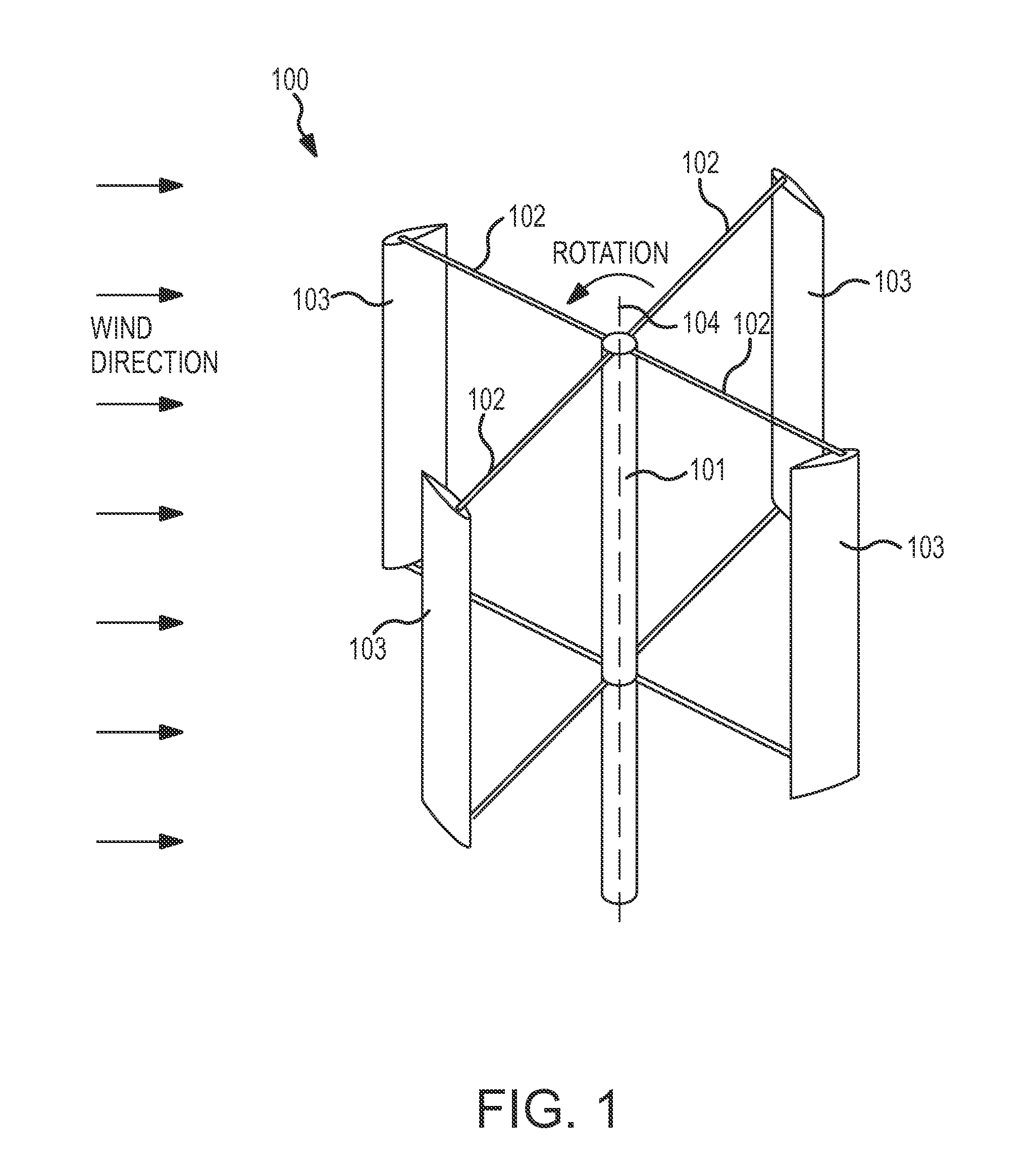
[0028]FIG. 1 shows a portion of a vertical axis wind turbine 100 according to an embodiment of the invention. It should be appreciated that the electrical generator of the VAWT 100 is not shown for the purpose of clarity. The electrical generator used may comprise any suitable electrical generator as is known in the art. The VAWT ...


PUM


Abstract

A vertical axis wind turbine (100) is provided according to an embodiment of the invention. The vertical axis wind turbine (100) comprises a rotatable shaft (101) and one or more arms (102) coupled to and extending from the rotatable shaft (101). The vertical axis wind turbine (100) further comprises one or more blades (103) coupled to the one or more arms (102). A high lift device (210) is coupled to each of the one or more blades (103). The high lift device (210) is adapted to control a lift-to-drag ratio of the blade (103).

Description

CROSS-REFERENCE TO RELATED APPLICATION[0001]This application claims priority from U.S. Provisional Patent Application No. 61 / 092,107, filed Aug. 27, 2008, entitled “Vertical Axis Wind Turbine”, the contents of which are incorporated herein by reference.TECHNICAL FIELD[0002]The present invention relates to a vertical axis wind turbine, and more particularly, to a vertical axis wind turbine including rotatable blades adapted to optimize the blade's lift-to-drag ratio.BACKGROUND OF THE INVENTION[0003]With the increasing costs and decreasing availability of fuels typically used to produce power, wind turbines are being implemented in greater numbers. Wind turbines typically operate by using the kinetic energy of air flow across a propeller to cause the propeller to rotate. The propeller produces electricity using an electric generator.[0004]Wind turbines typically fall into two categories, horizontal-axis wind turbines (HAWTs) and vertical-axis wind turbines (VAWTs). As the name implies...

Claims


Application Information

Patent Timeline
Patent Type & Authority Applications(United States)
IPC IPC(8): F03D3/06F03D11/00
CPCF03D3/068Y02E10/74F05B2240/31F05B2240/231
Inventor SNEERINGER, CHARLES P.
Owner SNEERINGER CHARLES P
Why Eureka
Try Eureka