Electrical connector having datum block facilitating precise alignment

Inactive Publication Date: 2010-03-04
HON HAI PRECISION IND CO LTD
View PDF7 Cites 2 Cited by
  • Summary
  • Abstract
  • Description
  • Claims
  • Application Information

AI Technical Summary

Benefits of technology

[0007]Accordingly, an object of the present invention is to provide an

Problems solved by technology

When the insulative housing is formed through the molding process, the longitudinal sidewalls of the insulative housing are vulnerable to vary from straightness because of the plastic material, thereby effecting ali

Method used


Image

  • Electrical connector having datum block facilitating precise alignment
  • Electrical connector having datum block facilitating precise alignment
  • Electrical connector having datum block facilitating precise alignment

Examples


Example

[0018]Reference will now be made to the drawings to describe the present invention in detail.

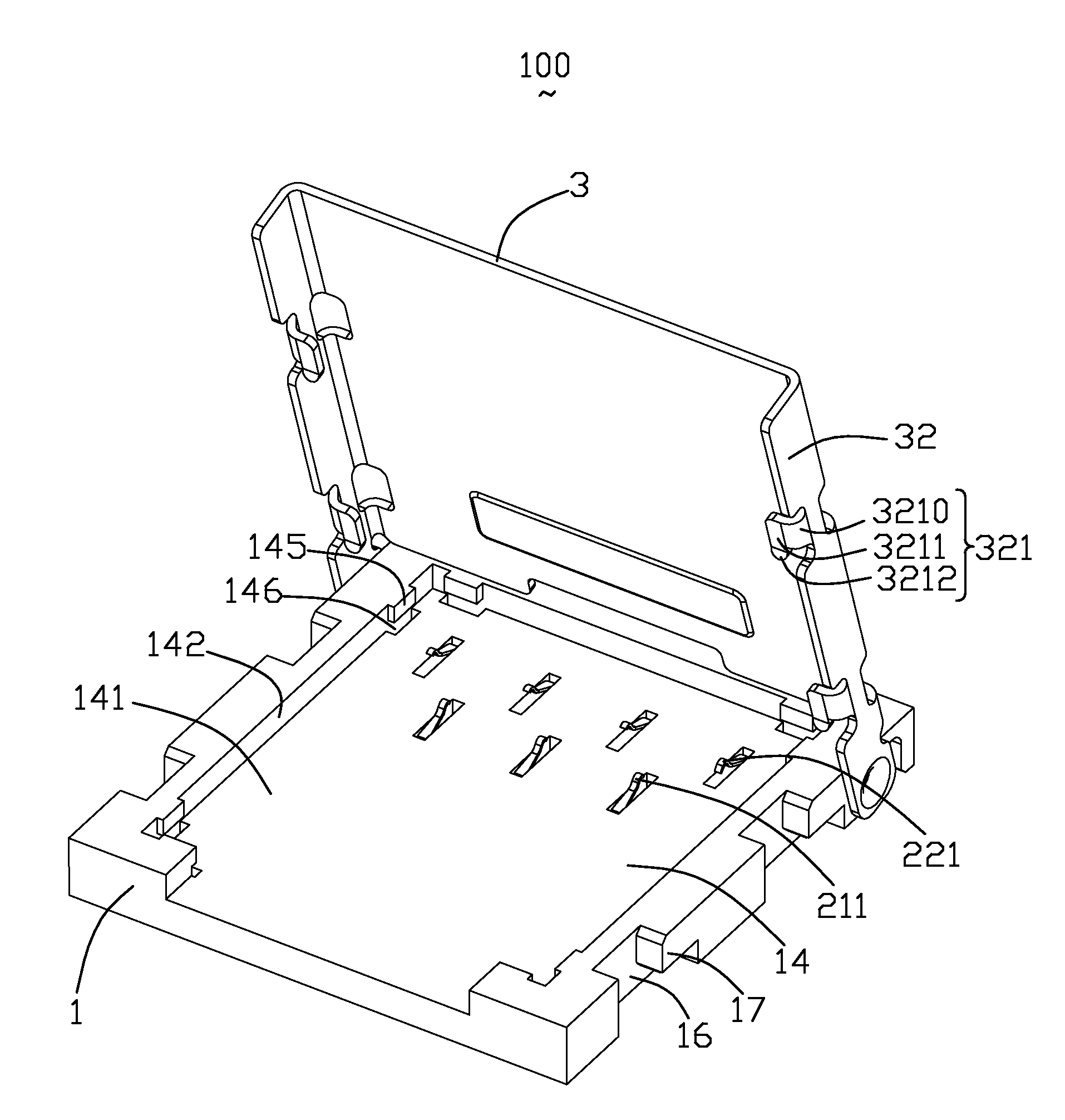
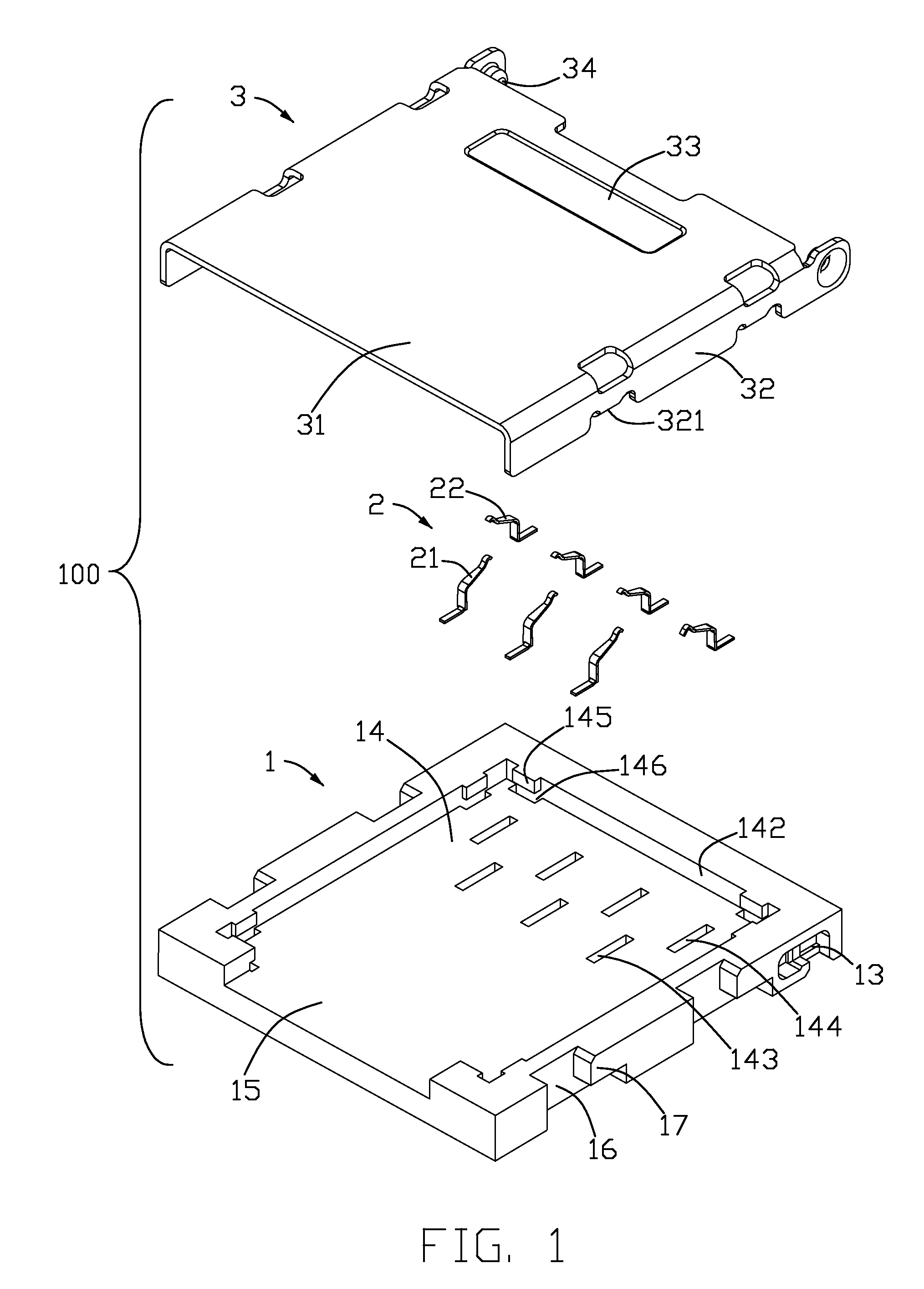
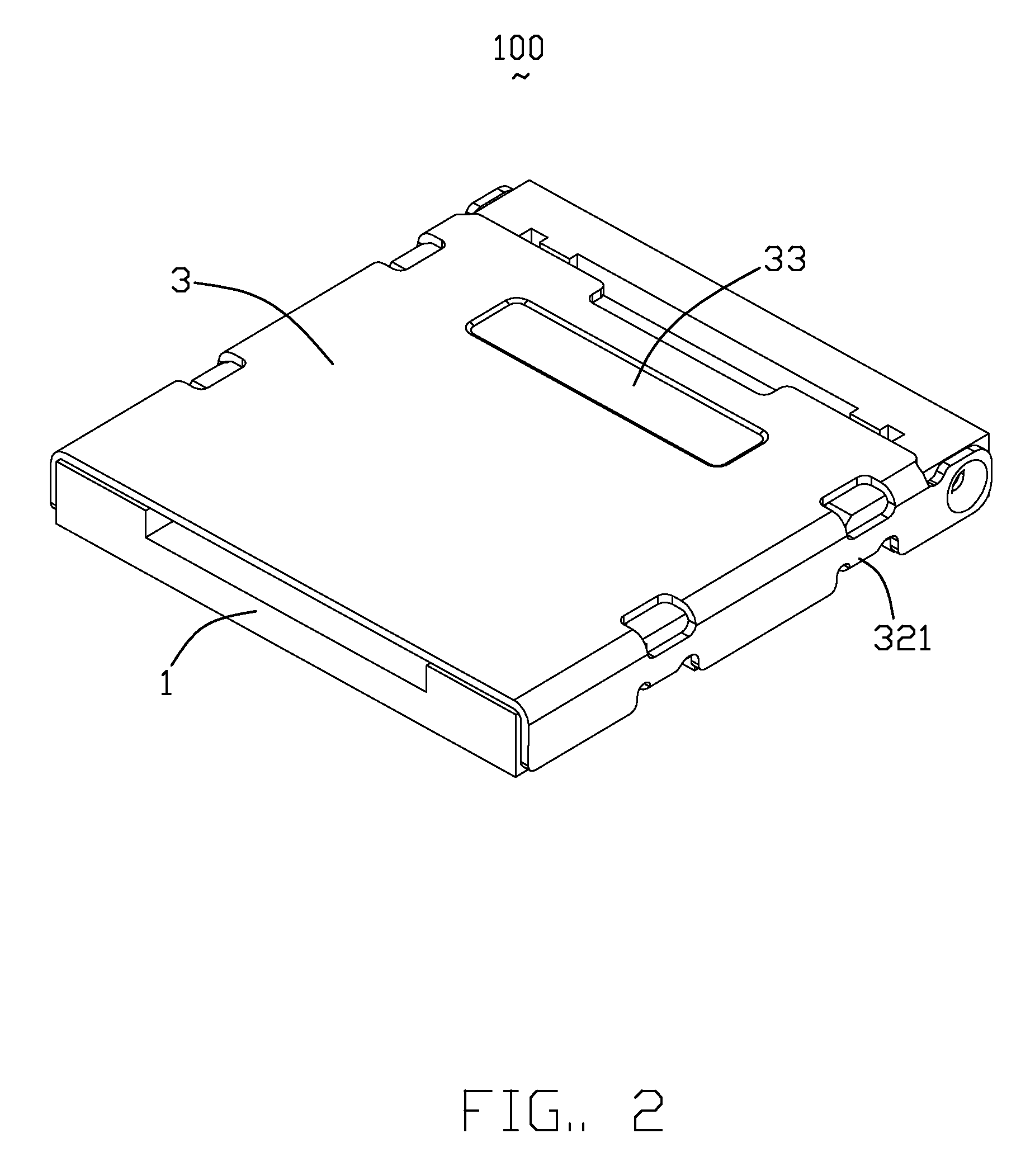
[0019]Referring to FIGS. 1-4, an electrical connector 100 in accordance with the present invention is used to convert electric and optical signal from a module (not shown) to a circuit substrate (not shown). The electrical connector 100 comprises an insulative housing 1, a plurality of contacts 2 received in the insulative housing 1 and a cover 3 assembled on the insulative housing 1.

[0020]The insulative housing 1 is configured to a rectangular shape and comprises a bottom wall 141, four sidewalls 142 extending upwardly from the bottom wall 141. The bottom wall 141 and the four sidewalls 142 together formed a receiving space. The bottom wall 141 defines a row of first passageways 143 and a row of second passageways 144 parallel to each other. The contacts 2 comprises a plurality of first contacts 21 received in the first passageways 143 and a plurality of second contacts 22 received in the s...


PUM


Abstract

An electrical connector (100) used to transmit electric and optical signal from a module to a circuit substrate comprises an insulative housing (1), a plurality of contacts (2) received in the insulative housing (1) and a cover (3) being assembled on the insulative housing (1) and can move between an opened position to a closed position, the insulative housing (1) comprises a bottom wall (141) and a plurality of sidewalls (142) extending upwardly from the bottom wall (141), each of the sidewalls (142) each defines a plurality of datum blocks (145) and the inner surface of the datum (145) on one sidewall (142) are located in one plane, the datum blocks (145) together formed a space (14) to receive the module.

Description

BACKGROUND OF THE INVENTION[0001]1. Field of the Invention[0002]The present invention relates to an electrical connector, and more particularly, to an electrical connector having longitudinal sidewalls each has at least a datum block ensuring precise contact interconnection alignment thereof.[0003]2. Description of the Prior Art[0004]TW M 244598 issued to Lu on Sep. 21, 2004 discloses a conventional electrical connector for electrically connecting a module with a PCB. The electrical connector comprises a socket body having a number of terminals received therein and a metallic cover assembled to the socket body. The socket body comprises a bottom wall and two sidewalls extending upwardly from the bottom wall. The bottom wall and the sidewalls form a space for disposing a module therein. The cover defines a slot and the side surface of the side wall defines a pinshaft received in the slot and can move in the slot.[0005]The space is used for accommodating the module. When the insulativ...

Claims


Application Information

Patent Timeline
IPC IPC(8): H01R12/00H01R13/44
CPCG06K7/003H01R12/7076
Inventor HSU, SHUO-HSIUMA, HAO-YUN
Owner HON HAI PRECISION IND CO LTD
Why Eureka
Try Eureka