Anodized locking plate components

a technology of locking plate and components, applied in the field of orthopedic plates and locking screws, can solve the problems of surgeons having to cut the screws out of the orthopedic plates and the bone, and surgeons have encountered great difficulty, and achieve the effect of reducing galling or cold welding

Inactive Publication Date: 2010-03-04
ZIMMER INC
View PDF6 Cites 107 Cited by
  • Summary
  • Abstract
  • Description
  • Claims
  • Application Information

AI Technical Summary

Benefits of technology

[0007]The present invention provides an orthopedic assembly including a plate and a locking screw that interlocks with the plate to secure the plate to a bone while the bone heals. To minimize galling or cold welding within an engagement region of the orthopedic assembly, an anodized coating, such as a Type II anodized coating, may be applied to both engaging surfaces of the engagement region. To avoid having to mask portions of the plate and the locking screw outside of the engagement region during the coating process, the anodized coating may be applied to the entire plate and the entire locking screw.

Problems solved by technology

Although locking the screw to the orthopedic plate provides enhanced fixation between the screw and the orthopedic plate, surgeons have encountered great difficulty when later attempting to separate the screw from the orthopedic plate.
When these solutions fail, however, the surgeon may have to cut the screw out of the orthopedic plate and the bone.

Method used


Image

  • Anodized locking plate components
  • Anodized locking plate components
  • Anodized locking plate components

Examples


example 1

1. Example 1

Removal Torque vs. Seating Torque

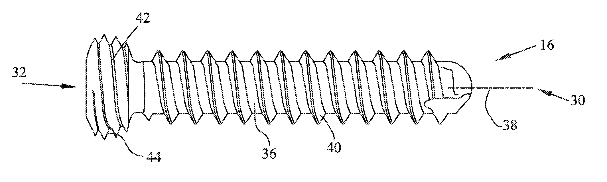
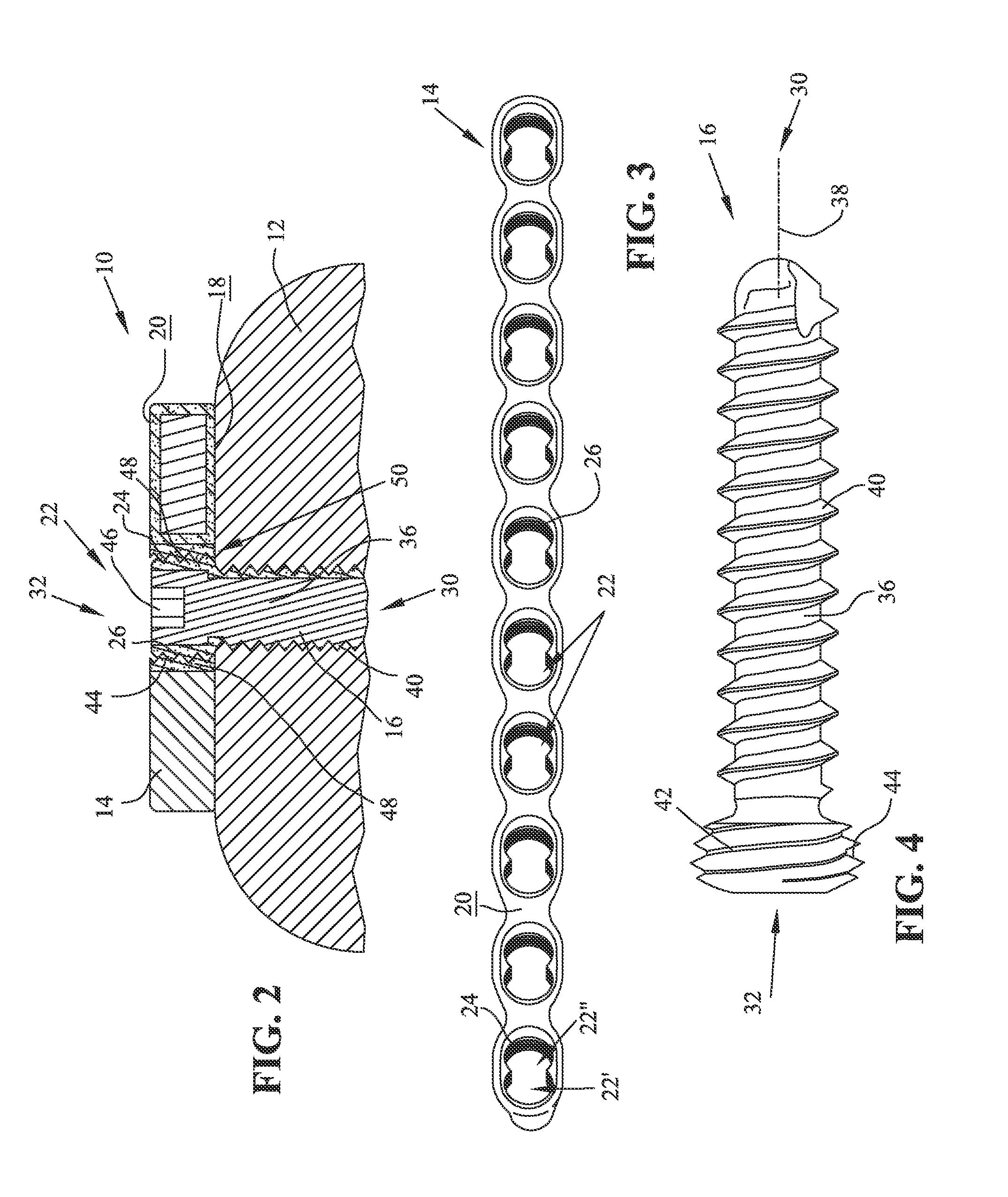
[0045]Combinations of various locking screws and plates were prepared as set forth in Table 1 below. Each locking screw was 40 mm in total length and 3.5 mm in diameter. Each plate included ten bores, each bore having dual locking holes. Three to five locking screws were tested per plate in each category, each locking screw being assigned to a different locking hole of the plate. Anodized samples were Type II anodized according to AMS 2488D or blue anodized according to DPP5358 Rev. 001024 by Danco Anodizing, Inc. of Warsaw, Ind.

TABLE 1PlateLocking ScrewsSubstrateCoatingSubstrateCoatingMaterialTypeMaterialType1Ti—6A1—4V AlloyNoneTi—6A1—4V AlloyBlueAnodized2Ti—6A1—4V AlloyNoneTi—6A1—4V AlloyType IIAnodized3Ti—6A1—4V AlloyType IITi—6A1—4V AlloyBlueAnodizedAnodized4Ti—6A1—4V AlloyType IITi—6A1—4V AlloyType IIAnodizedAnodized5Ti—15Mo AlloyType IITi—6A1—4V AlloyType IIAnodizedAnodized

[0046]Each of the five locking screw and plate combinations ...

example 2

2. Example 2

Removal Torque After Fatigue Testing

[0055]Referring back to Table 1 above, two Category 4 assemblies were prepared. Each assembly included four locking screws and a plate. A hex driver mated to a calibrated digital torque wrench was used to seat the locking screws at a torsional seating load of approximately 2.5 N-m. The assemblies were subjected to fatigue tests that occurred in Ringer's solution at 37° C. and that continued for 2 million cycles. Following fatigue testing, the locking screws were removed with the calibrated torque wrench. The torsional load required for removal was measured and recorded. The results are provided in Table 2 below.

TABLE 2AssemblyScrewTorsional Removal LoadNumberNumber(N-m)111.7121.8131.6541.56211.8121.3931.6241.50

[0056]Even after fatigue testing, the torsional load required to remove the Tivanium™ Ti-6Al-4V alloy Type II anodized locking screws from the Tivanium™ Ti-6Al-4V alloy Type II anodized plates was less than the torsional seating ...


PUM


Abstract

An orthopedic assembly including a plate and a locking screw that interlocks with the plate to secure the plate to a bone while the bone heals. To minimize galling or cold welding within an engagement region of the orthopedic assembly, an anodized coating, such as a Type II anodized coating, may be applied to both engaging surfaces of the engagement region. To avoid having to mask portions of the plate and the locking screw outside of the engagement region during the coating process, the anodized coating may be applied to the entire plate and the entire locking screw.

Description

CROSS REFERENCE TO RELATED APPLICATION[0001]This application claims priority from U.S. Provisional Patent Application No. 61 / 093,195, entitled “Minimization of Galling Using Type II Anodized Locking Plate Components,” filed on Aug. 29, 2008, by the same inventors hereof, the disclosure of which is expressly incorporated herein by reference.BACKGROUND[0002]1. Field of the Invention[0003]The present invention relates to an orthopedic assembly for supporting a bone while the bone heals. More particularly, the present invention relates to an orthopedic plate and locking screws for securing the orthopedic plate to the bone while the bone heals.[0004]2. Description of the Related Art[0005]An orthopedic plate may be secured across a bone fracture to reduce the fracture and to provide support to the bone. The orthopedic plate may include a plurality of holes therein for receipt of screws which are drilled into the bone to secure the orthopedic plate to the bone across the fracture line.[000...

Claims


Application Information

Patent Timeline
Patent Type & Authority Applications(United States)
IPC IPC(8): A61B17/80A61B17/86A61B17/88
CPCA61B17/8057A61B2017/00831A61B17/863
Inventor PRICE, GREGORY G.COMPTON, RICHARD C.
Owner ZIMMER INC
Why Eureka
Try Eureka