Bore liner for undersea hydraulic coupling

a hydraulic coupling and bore liner technology, applied in the direction of couplings, hose connections, cable terminations, etc., can solve the problems of galling of the surface of the probe and/or bore, serious galling of the male and/or female coupling members, and more likely to gall. , to achieve the effect of reducing further galling and reducing the surface galling

Active Publication Date: 2009-08-18
NAT COUPLING
View PDF37 Cites 20 Cited by
  • Summary
  • Abstract
  • Description
  • Claims
  • Application Information

AI Technical Summary

Benefits of technology

[0011]The present invention provides an undersea hydraulic coupling with a removable bore liner. The bore liner may be a removable, durable polymer sleeve that fits in at least part of the bore of a female undersea hydraulic coupling member. The bore liner may be integral with one or more radial seals that extend radially inwardly from the bore liner and seal between the male and female coupling members. Part of the bore liner may be engaged to the female undersea hydraulic coupling member using threads on the outer circumference of the bore liner, a ridge, ring or groove on the outer surface of the bore liner, a dovetail interfit between the bore liner and the female coupling member and / or seal retainer, or various other restraining means. The bore liner may be used to retrofit undersea hydraulic couplings to help minimize galling and reduce further galling of the sealing surfaces of the male and / or female coupling members.

Problems solved by technology

Insertion of the male coupling member into the bore of the female coupling member, or removal of the male coupling member from the bore, may result in galling of the surfaces of the probe and / or bore.
Galling may be caused, for example, by significant misalignment, or even very slight misalignment, of the male and female coupling members during their engagement or disengagement.
In general, galling of the male and / or female coupling members is a serious problem because of damage to the sealing surfaces that are important to maintain fluid tight seals to block leakage of hydraulic fluid and / or entry of seawater into the coupling at high pressure.
Additionally, after a sealing surface of either coupling member becomes galled, it may be more likely to gall again.

Method used


Image

  • Bore liner for undersea hydraulic coupling
  • Bore liner for undersea hydraulic coupling
  • Bore liner for undersea hydraulic coupling

Examples


first embodiment

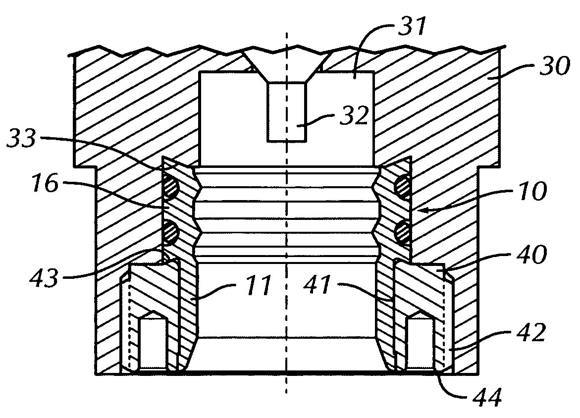
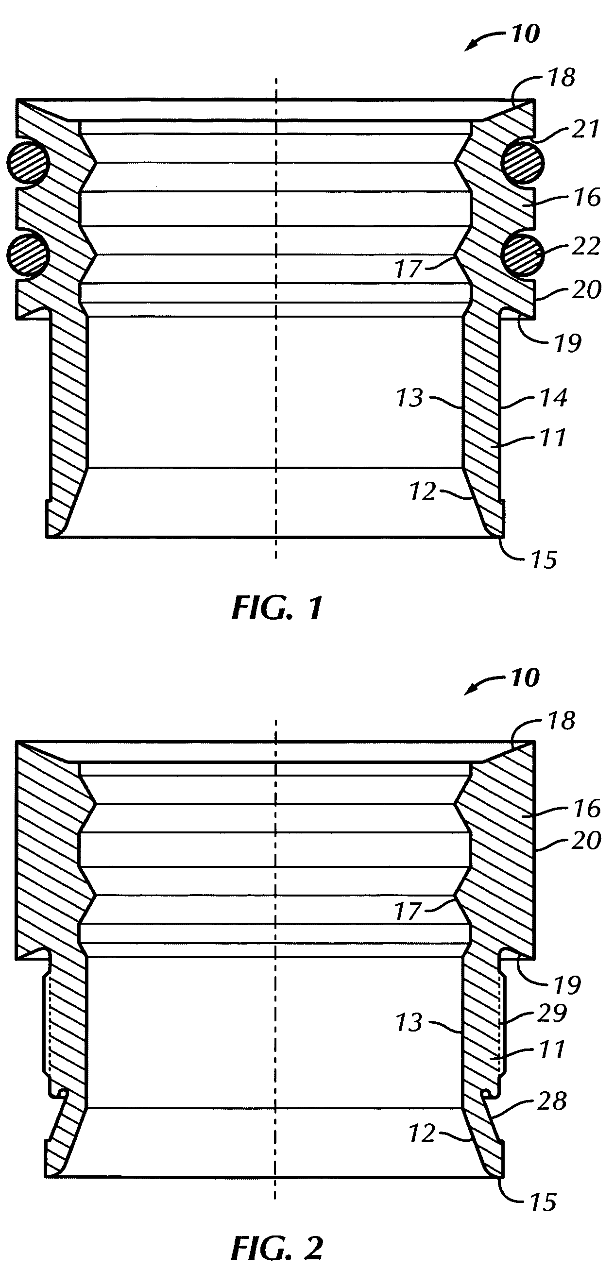
[0030]As shown in FIG. 1, in a first embodiment bore liner 10 may include liner section 11 and seal section 16. The liner section has an inner diameter 13 and an outer diameter 14. In one embodiment, end face 15 of the liner section may have a tapered portion 12 at the inner diameter thereof. The seal section may include one or more sealing surfaces 17 that project radially inwardly further than the inner diameter of the bore liner. Thus, the inner diameter of sealing surfaces 17 should be less than the inner diameter of the liner section. The sealing surfaces may be dimensioned to engage the outer surface of the male coupling member or probe. In one embodiment, the seal section may have outer shoulders 18, 19 that may be dimensioned to interfit with a female coupling member to help secure the bore liner thereto. For example, the shoulders may provide a dovetail interfit. The seal section has outer diameter 20 and also may include one or more grooves 21 in which O-rings 22 may be po...

third embodiment

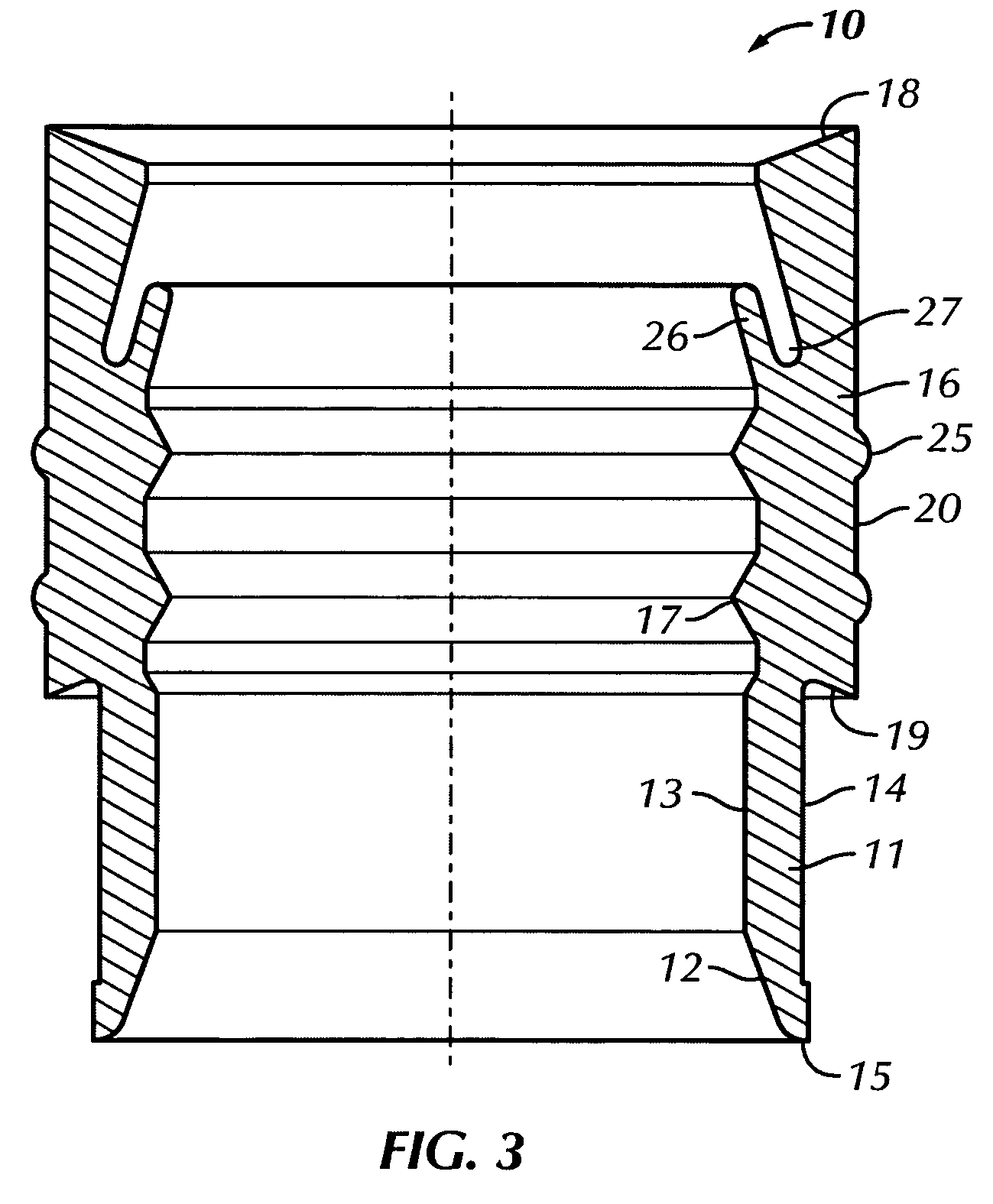
[0032]As shown in FIG. 3, a third embodiment with the same elements identified with the same reference numbers as the previous embodiments with the following differences. Outer diameter 20 of seal section 16 may have one or more seal projections 25 to seal with the female coupling member. The seal section also may have sealing lip 26 which may be pressure energized by fluid pressure in cavity 27 to urge the sealing lip against the male coupling member.

fourth embodiment

[0033]As shown in FIG. 4, a fourth embodiment with the same elements identified with the same reference numbers as the previous embodiments with the following differences: This embodiment includes sealing lip 26 and interlocking section 28.


PUM

PropertyMeasurementUnit
radial thicknessaaaaaaaaaa
internal diameteraaaaaaaaaa
outer diameteraaaaaaaaaa

Abstract

An undersea hydraulic coupling member having a bore liner that protects the coupling members from galling during assembly or disassembly. The bore liner is removable from the bore of a female undersea hydraulic coupling member. The bore liner may be integral with a seal section that may seal with a male undersea hydraulic coupling member. The bore liner also may have an outer diameter configured to engage and interlock with the bore in which the bore liner is positioned.

Description

BACKGROUND OF THE INVENTION[0001]1. Field of the Invention[0002]This invention relates, in general, to hydraulic couplings, and specifically to hydraulic couplings used in undersea drilling and production applications. More particularly, the invention involves a removable bore liner for an undersea hydraulic coupling member.[0003]2. Description of Related Art[0004]Subsea hydraulic couplings are old in the art. The couplings generally consist of a male member and a female member with seals to seal the junction between the male and female members. The female member generally has a cylindrical body with a relatively large diameter bore at one end and a relatively small diameter bore at the other. The small bore facilitates connections to hydraulic lines, while the large bore contains the seals and receives the male portion of the coupling. The male member includes a probe section insertable into the large bore of the female member. According to various embodiments of the device, the se...

Claims


Application Information

Patent Timeline
Patent Type & Authority Patents(United States)
IPC IPC(8): F16L21/03F16L17/03F16L47/08F16L33/16
CPCF16L33/16F16L29/04F16L37/30
Inventor SMITH, III, ROBERT E.
Owner NAT COUPLING
Why Eureka
Try Eureka