Method and device for loading a stent applicator

a technology for stents and applicators, applied in the field of methods and devices for loading stents, can solve the problems of reducing the diameter of the stent, unable to construct a longitudinal fold that can reversibly reconstruct itself, and unable to meet the needs of patients, and achieves the effects of simple and inexpensive production, no risk of injury for users, and convenient handling of the devi

Inactive Publication Date: 2010-03-04
KARL STORZ GMBH & CO KG
View PDF7 Cites 4 Cited by
  • Summary
  • Abstract
  • Description
  • Claims
  • Application Information

AI Technical Summary

Benefits of technology

[0021]With the inventive device it is now possible for the first time to move even wire stents into a stent applicator, almost completely without manual handling and thus without risk of injury for the user.
[0022]According to a preferred embodiment of the invention it is proposed that the cylinder should be configured as a tube slit in the longitudinal direction with a handle mounted on the proximal end, so that the slit reaches as far as the distal end of the cylinder tube. This type of configuration of the cylinder allows for ease of handling the device as well as simple and inexpensive production.
[0023]According to the invention, the handle for operating the cylinder is advantageously configured as a disc mounted on the proximal end of the cylinder tube, so that the disc-shaped configuration of the handle ensures good and firm gripping of the handle.

Problems solved by technology

These wire stents can be reduced in diameter by means of lateral pressure, but it is not possible, as a rule, to construct a longitudinal fold that can reversibly reconstruct itself because of the material rigidity.
This manual loading is very burdensome because the stent tends to exceed the diameter of the applicator and thus on being pushed inward it can become jammed.
In addition, on the ends of the wire-mesh stents there are usually sharp wires extending, on which the operator can easily become injured while inserting the stent into the stent applicator.

Method used


Image

  • Method and device for loading a stent applicator
  • Method and device for loading a stent applicator
  • Method and device for loading a stent applicator

Examples


Embodiment Construction

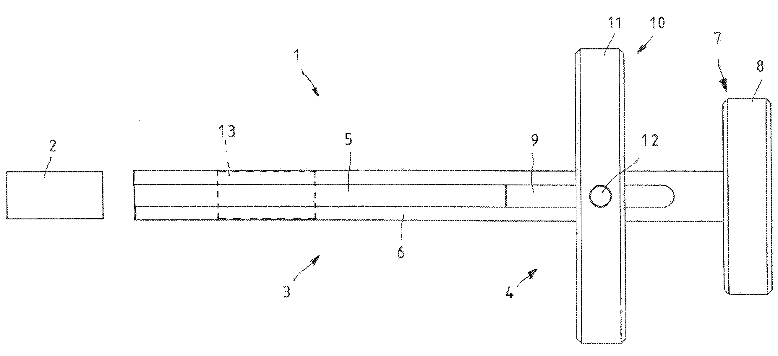
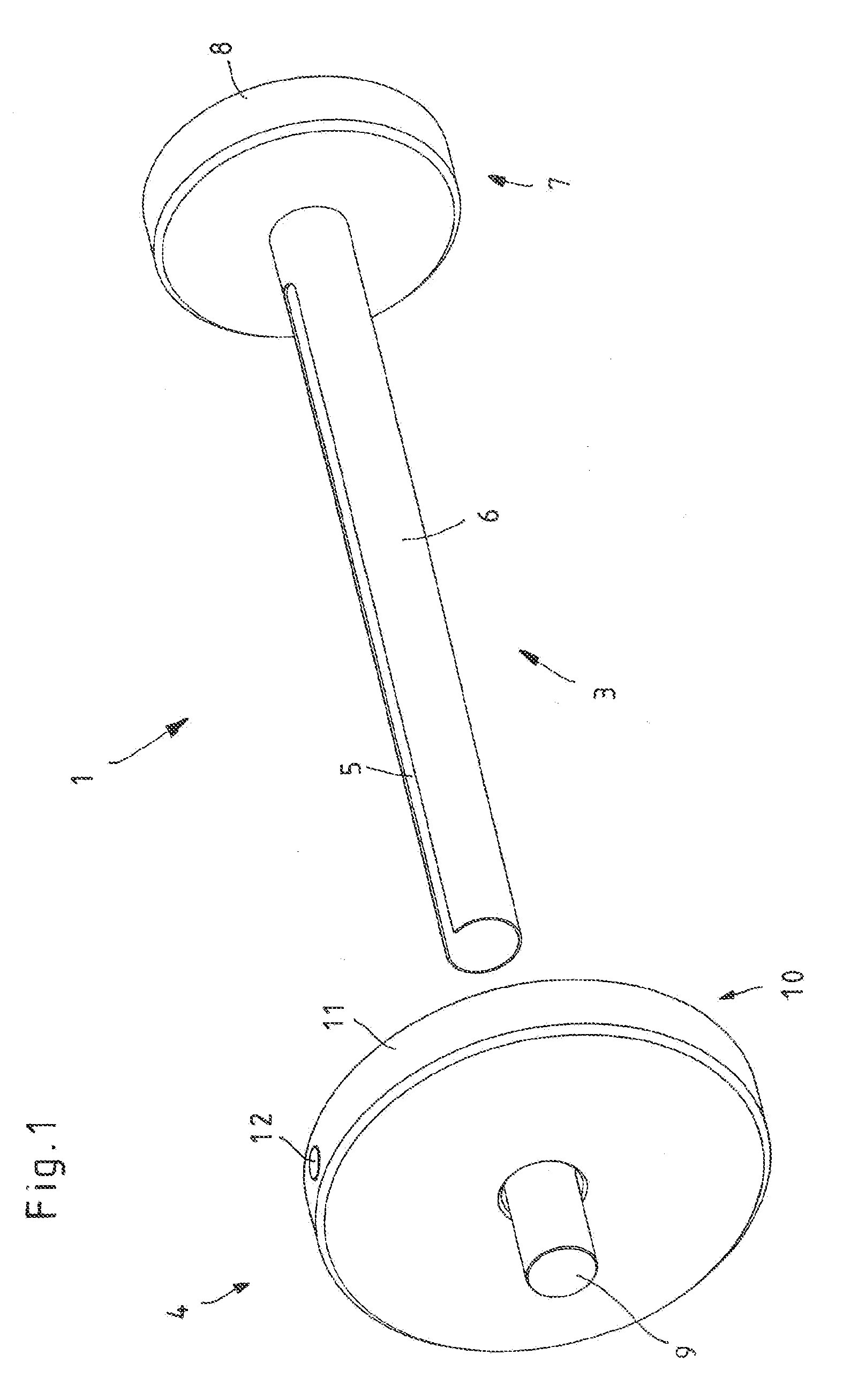
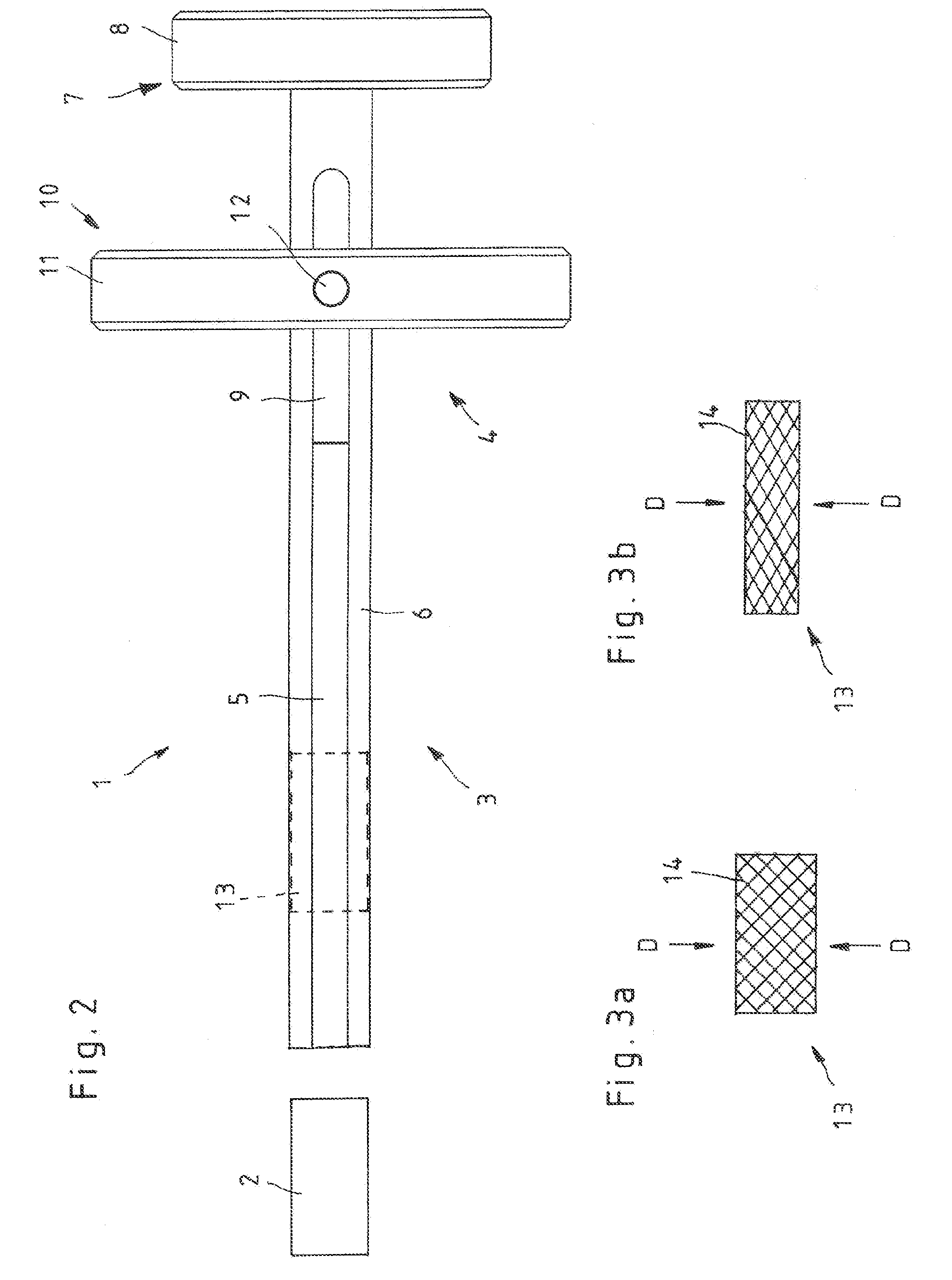
[0032]The loading device 1 for loading a stent applicator 2, shown in FIGS. 1 and 2, consists essentially of a cylinder-piston arrangement that includes a cylinder 3 and a piston 4.

[0033]As can be seen from FIGS. 1 and 2, the cylinder 3 is configured as a tube 6 that includes at least partially a longitudinal slit 5, so that the longitudinal slit 5 reaches to the distal end of the cylinder tube 6. Positioned on the proximal end of the cylinder tube 6 is a handle 7 which is configured in the illustrated embodiment as a disc 8 mounted on the proximal end of the cylinder tube 6.

[0034]The piston 4 is configured as a rod-shaped plunger 9 that is essentially form-lock mounted in assembled state in the loading device 1 and can be slid in the cylinder tube 6 in the longitudinal direction of the cylinder tube 6. Positioned at the proximal end of the piston is a handle 10 which is configured in the illustrated embodiment as a disc 11 that is mounted on the cylinder tube 6 and is connected by ...


PUM


Abstract

A method and a device for loading a stent applicator that makes possible the loading of the stent applicator with simple handling and without risk of injury. The method is characterized by the steps of Exerting a lateral pressure on the stent to reduce its diameter, Inserting the compressed stent into a loading device that includes a cylinder-piston arrangement, At least partially inserting the loading device into the stent applicator, and Loading the stent applicator with the stent by pushing the components—cylinder and piston—of the loading device relative to one another.

Description

CROSS-REFERENCE TO RELATED APPLICATIONS[0001]The present application claims priority of German patent application No. 10 2008 036 205.0 filed on Aug. 2, 2008.FIELD OF THE INVENTION[0002]The invention relates to a method and a device for loading a stent applicator.BACKGROUND OF THE INVENTION[0003]A stent is understood to refer to a small tube inserted endoscopically during surgery for bridging or drainage in cases of stenoses, strictures, and tumors. Stents take the form of tube-shaped prostheses produced from various materials that are compatible with the human body and serve, after the endoscopic or radiological implantation or in short-term vessel stenoses caused by arteriosclerosis, to bridge or to contain the lumen of a hollow organ.[0004]Patent DE 10249 927 B3, for instance, discloses a device for compressing tubular endoprostheses as well as for inserting a compressed endoprosthesis into an application tube. This known device serves to compress stents made of pliable elastic m...

Claims


Application Information

Patent Timeline
Patent Type & Authority Applications(United States)
IPC IPC(8): A61F2/84A61F2/95
CPCA61F2002/9522A61F2/95A61F2/9522A61F2/9526
Inventor PILZ, KEVINHERMLE, RAINER
Owner KARL STORZ GMBH & CO KG
Why Eureka
Try Eureka