Ball joint for pipe connection and pipe connection

a ball joint and pipe technology, applied in the direction of couplings, mechanical equipment, constructions, etc., can solve the problems of manual alignment of personnel and the risk of injury to nearby personnel, and achieve the effect of evenly dispersing forces

Inactive Publication Date: 2021-09-16
LEO DYNAMISCHE INVESTERING
View PDF0 Cites 0 Cited by
  • Summary
  • Abstract
  • Description
  • Claims
  • Application Information

AI Technical Summary

Benefits of technology

[0008]Due to the decrease in inner diameter of the clamp when the segments are moved from the open position to the clamping position, both the inner shell part and the outer shell part are forced into alignment with the clamping segments during said movement. As a result, reliable clamping of the two shell parts by the clamp is achieved without requiring additional manual alignment by personnel during said movement, even when the inner and / or outer shell parts are fixed to corresponding pipe ends. The actuator which is arranged for driving movement of the segments can be remotely controlled by personnel from a safe distance, e.g. from a distance of at least 2 m, preferably from a distance of at least 5 m from the clamp. Thus, no persons have to be in the immediate vicinity of the ball joint during closing and / or opening thereof, substantially reducing the risk of injury. The ball joint according to the invention, which may weigh 5000 kg or more, is particularly suitable for connecting floating dredging hoses to each other, for instance hoses having outer diameters of about 1 m or more and / or wherein the hoses are used to transport sand- and rock-carrying water and / or sludge during dredging operations. The clamp is preferably adapted for clamping the inner and outer shell part substantially without deformation of the either shell part, allowing substantially rigid the inner and outer shell parts to be used which substantially do not deform during clamping.
[0035]According to a fourth aspect, the present invention provides a pipe connection assembly comprising a ball joint according to the invention, and further comprising: a first pipe with an end to which the outer shell part is attached and wherein said clamp is arranged around said outer shell part. The pipe, ball joint and outer shell part of this assembly can be assembled on land or on a vessel, after which the assembly can be placed in or on the water in a position where the inner shell part that is fixed to the second pipe can be inserted in the clamp. This allows very fast connection of pipes on sea and lakes, substantially without risk of injury to personnel.

Problems solved by technology

A drawback of the known ball joint is that personnel usually has to manually align and turn the yoke in order to ensure correct engagement of the bush when the yoke is rotated.
The close proximity of personnel to the yoke and bush is highly undesirable as hands or fingers may become trapped between moving parts of the joint, which may result in severe injury.
During connection of two pipes to each other at sea using the known ball joint, in particular when the pipes and / or joint are floatingly supported, waves and rough weather conditions also cause parts of the ball joint to move relative to each other, thus posing risk of injury to nearby personnel .

Method used


Image

  • Ball joint for pipe connection and pipe connection
  • Ball joint for pipe connection and pipe connection
  • Ball joint for pipe connection and pipe connection

Examples


Embodiment Construction

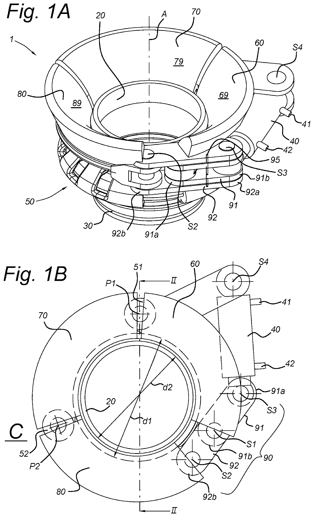
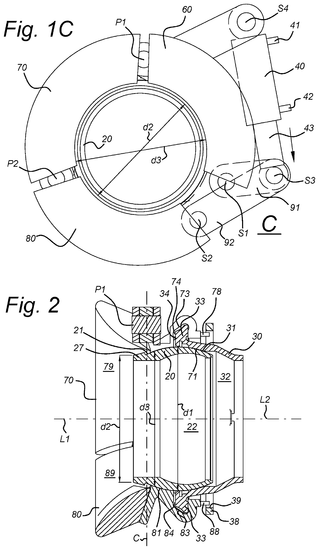
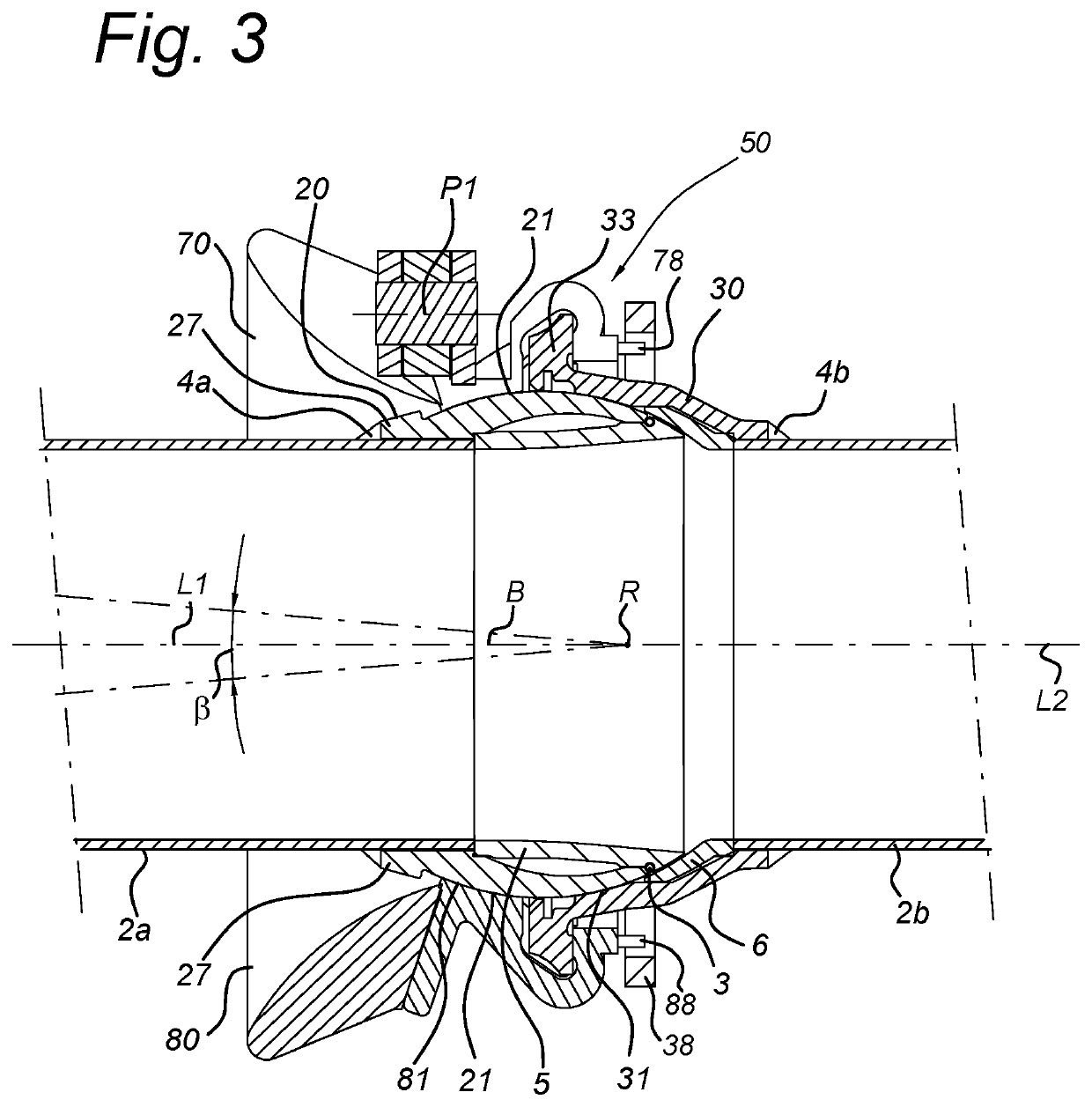
[0048]FIG. 1A shows an isometric view of a ball joint 1 according to the present invention. The ball joint 1 has a longitudinal centre axis A and comprises an inner shell part 20 and an outer shell part 30 for respective attachment to a first and second pipe, e.g. by means of welding, as well a clamp which comprises a first segment 60, intermediate segment 70 and last segment 80. The segments 60, 70, 80 are shown in FIG. 1A in a clamping position in which movement of the inner shell part 20 relative to the outer shell part 30 along a longitudinal centre line of either of these shell parts is substantially prevented while allowing rotation, e.g. between +15 and −15 degrees or between +5 and −5 degrees, between the respective longitudinal centre lines of these shell parts 20, 30. For driving movement of the segments from the clamping position to an open position and vice versa, the ball joint 1 is further provided with a remote controlled actuator 40 for moving the segments 60, 70, 80...


PUM


Abstract

Disclosed is a ball joint for connecting two floating pipes, the joint including an inner shell part, an outer shell part and a clamp with segments that are moveable in a common plane between an open position in which at least one of the shell parts is moveable into and out of the clamp, and a clamping position in which movement of both shell parts along the longitudinal centre lines is prevented. The ball joint is provided with a remote controlled actuator for driving movement of the segments between the open and closed position, without requiring nearby personnel to keep the shell parts aligned. Also disclosed is such a clamp and to a method of connecting such a ball joint to two pipes.

Description

FIELD OF THE INVENTION[0001]The present invention relates to a ball joint for a floating pipe connection, said ball joint comprising an inner shell part and an outer shell part which each define a respective longitudinal centre line and are rotatable in relation to one another between an aligned position in which the longitudinal centre lines coincide, and a rotated position in which the longitudinal centre lines are at an angle to each other which differs from zero, wherein said outer shell part is adapted for surrounding said inner shell part in a sealing manner with the inner shell part and outer shell part together enclosing a passage which extends from an opening in the inner shell part at one side of the ball joint to an opening in the outer shell part at another side of the ball joint. The ball joint is particularly suitable for connecting two pipes or hoses at sea or on a lake where the pipes / hoses and the ball joint connecting these are floatingly supported by a floatation ...

Claims


Application Information

Patent Timeline
Patent Type & Authority Applications(United States)
IPC IPC(8): F16L37/00F16L37/20F16L37/52F16L37/62
CPCF16L37/002F16L37/62F16L37/52F16L37/20E02F7/10
Inventor DE WIJN, BAREND JAN
Owner LEO DYNAMISCHE INVESTERING
Why Eureka
Try Eureka