
Arthrodesis implant for finger joints and related methods

a technology of arthrodesis implants and finger joints, applied in the field of arthroplastic implants, can solve the problems of pain, loss of motion, functional impairment, patient pain, and eventual functional loss, and achieve the effect of convenient implantation and effective treatmen

Active Publication Date: 2010-03-04
UPEX HLDG
View PDF43 Cites 57 Cited by
  • Summary
  • Abstract
  • Description
  • Claims
  • Application Information

AI Technical Summary

Benefits of technology

[0008]In view of the foregoing background, it is therefore an object of the present invention to provide a finger joint arthrodesis implant that is more effective and readily implanted.
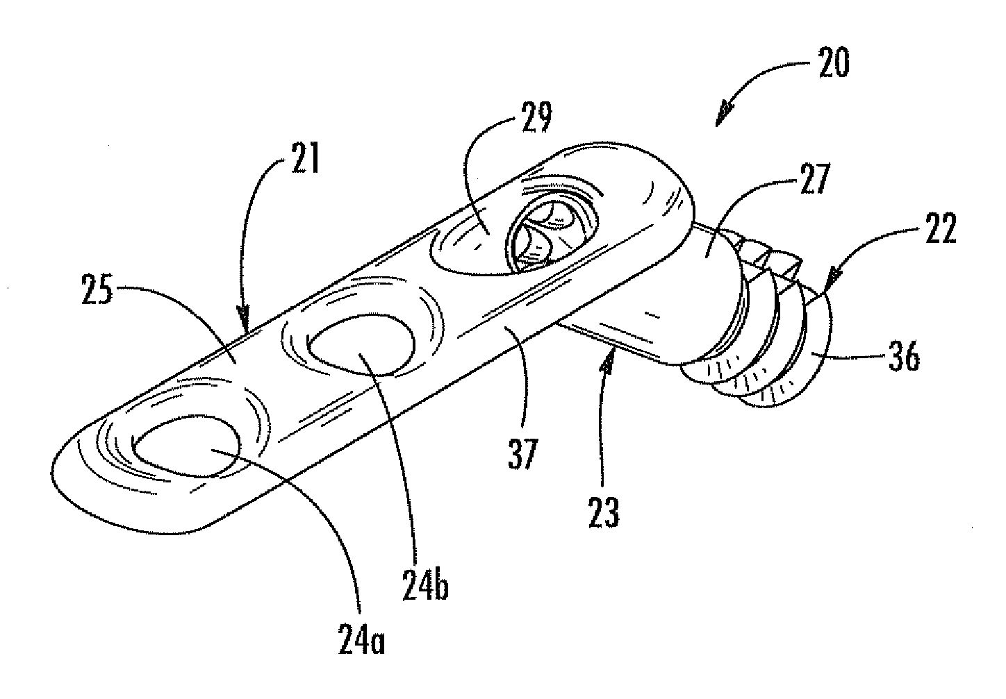
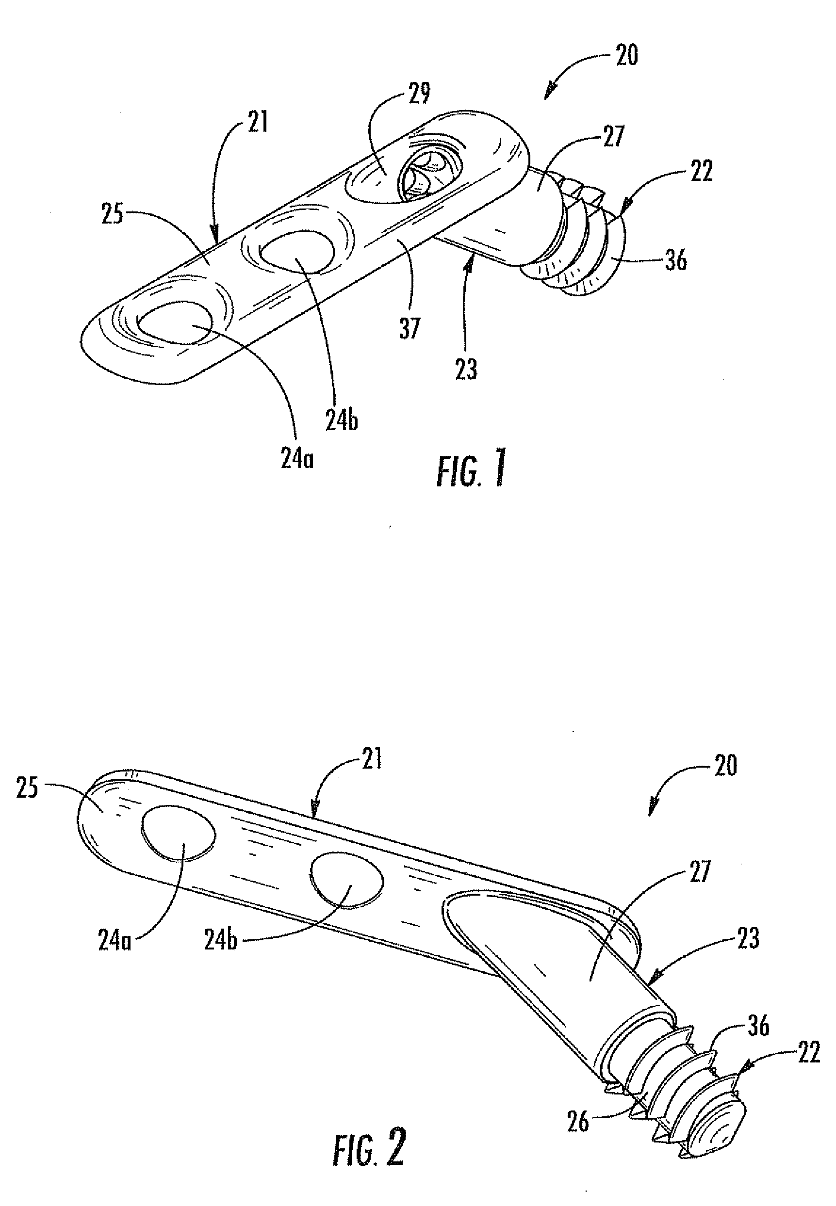
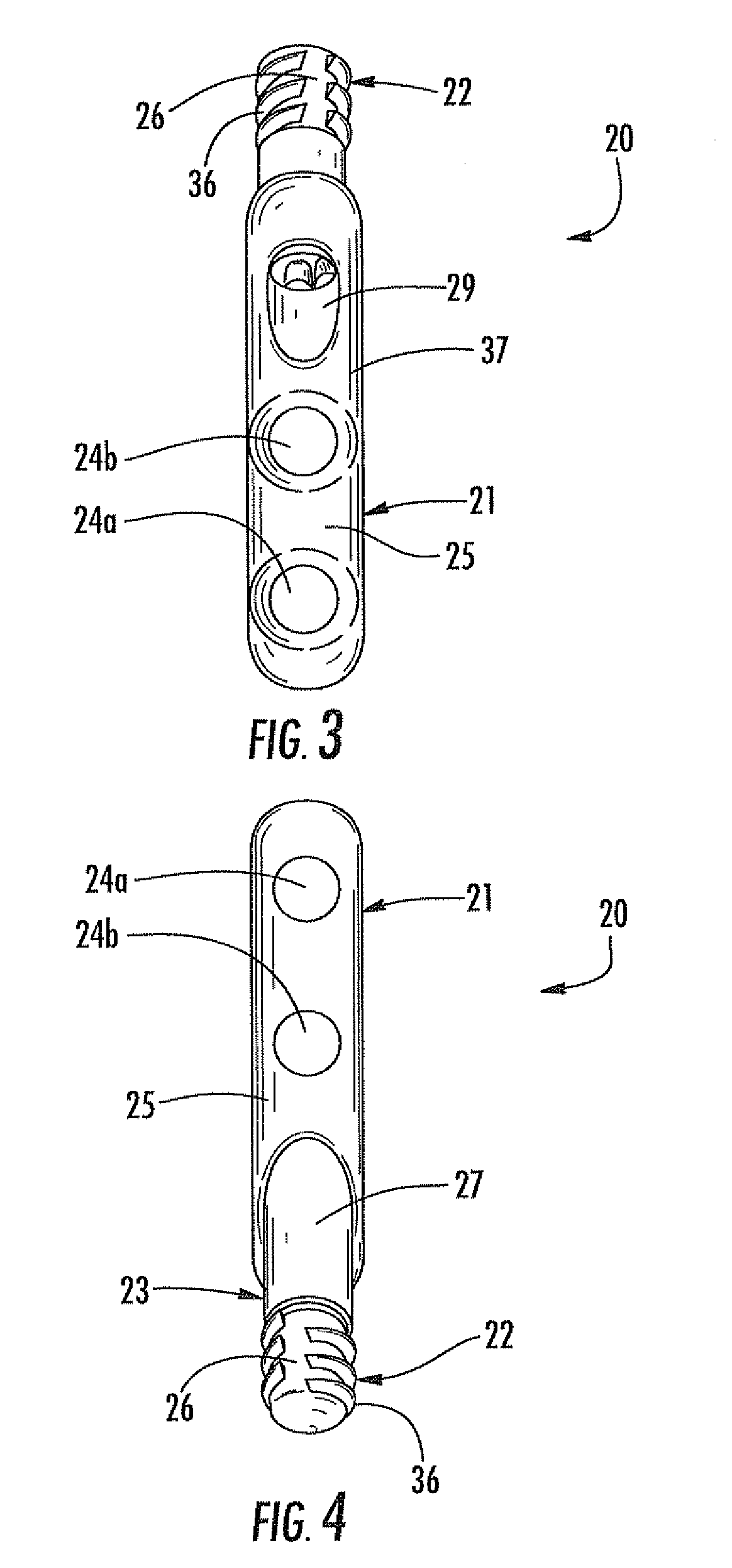
[0009]This and other objects, features, and advantages in accordance with the present invention are provided by an arthrodesis implant for a finger joint of a hand of a patient. The arthrodesis implant may include an extramedullary proximal anchor comprising a first member having at least one fastener-receiving passageway therethrough to receive at least one fastener to anchor the first member to an extramedullary portion of a proximal bone of the finger joint of the hand of the patient. The arthrodesis implant also includes an intramedullary distal anchor comprising a second member for being anchored within an intramedullary portion of a distal bone of the finger joint of the hand of the patient, and a coupling for securing the first and second members together. Advantageously, the arthrodesis implant accurately fuses the finger joint of the patient's hand.

Problems solved by technology

The clinical syndrome of Osteoarthritis, which is also known as degenerative arthritis or degenerative joint disease, is characterized by loss of articular cartilage on adjacent bony surfaces resulting in discomfort, loss of motion, and functional impairment.
As the bony surfaces become less protected by cartilage, the patient experiences pain, motion limitation, potential joint instability, and eventual functional loss.
These methods include potential drawbacks, for example, technically-demanding implantation procedure resulting in less than optimum accuracy, potential for subsequent hardware removal due to smooth wire migration or tension band “knot” irritation / abrasion on local tendons, and nonunion (or failure of the two bones to unite at the site of the desired fusion).

Method used


Image

  • Arthrodesis implant for finger joints and related methods
  • Arthrodesis implant for finger joints and related methods
  • Arthrodesis implant for finger joints and related methods

Examples


Embodiment Construction

[0027]The present invention will now be described more fully hereinafter with reference to the accompanying drawings, in which preferred embodiments of the invention are shown. This invention may, however, be embodied in many different forms and should not be construed as limited to the embodiments set forth herein. Rather, these embodiments are provided so that this disclosure will be thorough and completer and will fully convey the scope of the invention to those skilled in the art. Like numbers refer to like elements throughout.

[0028]Referring to FIGS. 1-12, an arthrodesis implant 20 for a finger joint of a hand of a patient is now described. As will be appreciated by those skilled in the art, the finger joint may comprise, for example, a proximal interphalangeal (PIP) joint, as defined by the coupling of the proximal and middle phalanges, or a metacarpophalangeal (MCP) joint, as defined by the coupling of the metacarpal bones and the proximal phalanges. The arthrodesis implant 2...


PUM


Abstract

An arthrodesis implant is for a finger joint of a hand of a patient. The arthrodesis implant may include an extramedullary proximal anchor including a first member having a fastener-receiving passageway therethrough to receive a fastener to anchor the first member to an extramedullary portion of a proximal bone of the finger joint of the hand of the patient. The arthrodesis implant may also include an intramedullary distal anchor having a second member for being anchored within an intramedullary portion of a distal bone of the finger joint of the hand of the patient, and a coupling for securing the first and second members together.

Description

FIELD OF THE INVENTION [0001]The present invention relates to the field of arthroplastic implants, and, more particularly, to proximal interphalangeal and metacarpophalangeal joint arthrodesis implants and related methods.BACKGROUND OF THE INVENTION [0002]The clinical syndrome of Osteoarthritis, which is also known as degenerative arthritis or degenerative joint disease, is characterized by loss of articular cartilage on adjacent bony surfaces resulting in discomfort, loss of motion, and functional impairment. In a similar fashion, inflammatory arthritis, for example, rheumatoid arthritis, results in loss of cartilage surfaces from both biochemical and mechanical means. As the bony surfaces become less protected by cartilage, the patient experiences pain, motion limitation, potential joint instability, and eventual functional loss.[0003]Interphalangeal joint arthritis is the development of Osteoarthritis at a patient's finger joint, for example, the proximal interphalangeal (PIP) jo...

Claims


Application Information

Patent Timeline
Patent Type & Authority Applications(United States)
IPC IPC(8): A61F2/42A61B17/04
CPCA61B17/8061A61B17/8685A61B17/863
Inventor GRAHAM, THOMAS JAMESBAMBERGER DO, H. BRENTCALANDRUCCIO, JAMES HOWARDHIGGINS, JAMESWIEDRICH, THOMAS A.FOCHT, LOUISE M.
Owner UPEX HLDG
Learn More