Method of moving data in logical volume, storage system, and administrative computer

Inactive Publication Date: 2010-03-04
HITACHI LTD
View PDF13 Cites 11 Cited by
  • Summary
  • Abstract
  • Description
  • Claims
  • Application Information

AI Technical Summary

Benefits of technology

[0013]It is an object of the present invention to provide method of moving data held in a logical volume, storage system, and administrative computer which can satisfy requirements of a thin provisioned volume the user intends if an event occurs in which the requirements of the thin provisioned volume cannot be satisfied when the thin provisioned volume is being used.

Problems solved by technology

If an event such as a fault occurs with connection, for example, between the first and second storage devices during operation of a thin provisioned volume offered by the technique disclosed in patent reference 1, some regions of the thin provisioned volume become inaccessible.
This presents the problem that it is impossible to satisfy the requirement of thin provisioned volume the user intends.

Method used


Image

  • Method of moving data in logical volume, storage system, and administrative computer
  • Method of moving data in logical volume, storage system, and administrative computer
  • Method of moving data in logical volume, storage system, and administrative computer

Examples


embodiment 1

(1) System Configuration of First Embodiment

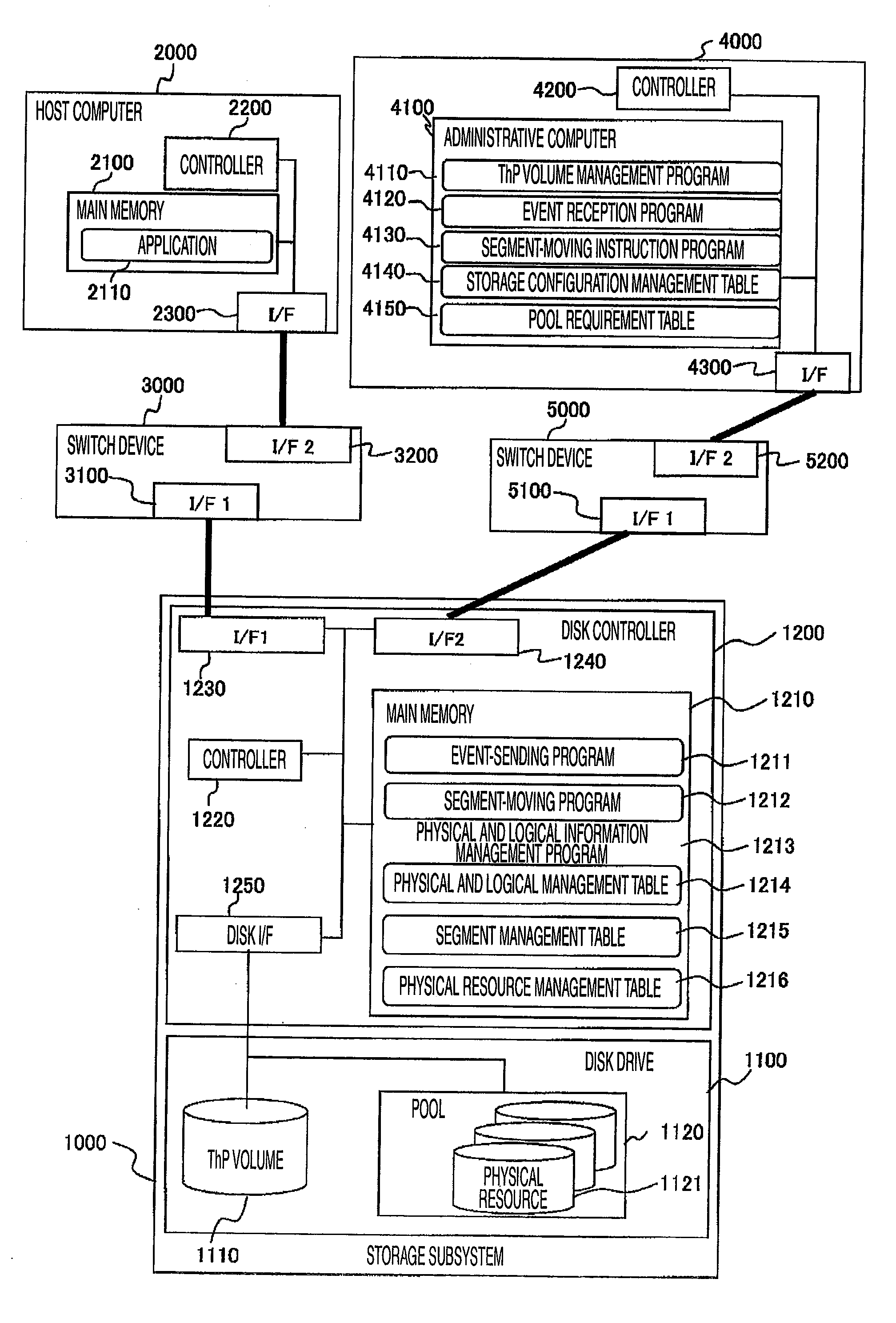
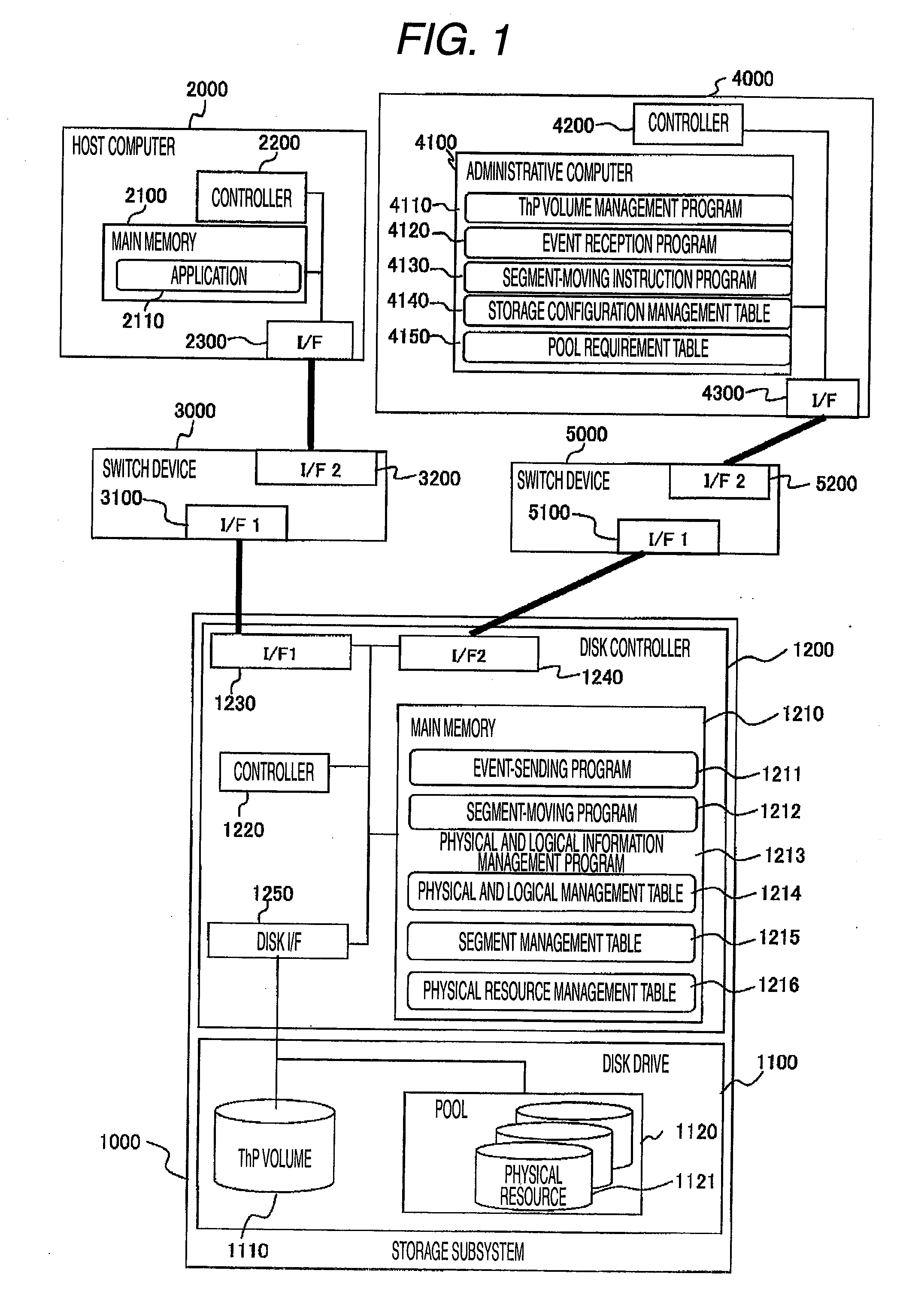
[0038]The configuration of a computer system according to the present embodiment is shown in FIG. 1. In the computer system of this embodiment, a storage subsystem 1000 and a host computer 2000 are interconnected by a switch device 3000.

[0039]In the present embodiment, the switch device 3000 is an FC (fibre channel) switch device forming a storage area network (SAN). The switch device 3000 may also be an IP (Internet Protocol) network or other switch device adapted for data communications.

[0040]The storage subsystem 1000 is connected with an administrative computer 4000 via a switch device 5000. In the present embodiment, the switch device 5000 is an IP switch device. The switch device 5000 may also be a storage area network (SAN) or other network for data communications. The switch device 3000 and switch device 5000 can be the same switch device. The host computer 2000 and administrative computer 4000 can be the same computer.

[0041]For co...

first embodiment

(2) Operation of First Embodiment

[0079]First, the subroutine performed by the event-sending program 1211 is described by referring to FIG. 8. An event in which the storage pool requirements are not satisfied has occurred with any regions of the thin provisioned volume 1110. The event-sending program 1211 detects a fault (S1000), for example. In the present specification, for convenience of illustration, the detected event is a fault. The detected event can be other events such as an instruction from other user or performance deterioration due to high load on the storage subsystem.

[0080]Then, the event-sending program 1211 sends information about a fault to the event reception program 4120. The information about the fault includes information for identification of a location where the fault has occurred, the contents of the fault, the importance, and the time at which the fault occurred. In the present specification, for convenience of illustration, it is assumed that a fault has occ...

second embodiment

(2) Operation of Second Embodiment

[0115]The second embodiment is similar in operation to the first embodiment except for the points described below. The subroutine performed by the event-sending program 6211 in the second embodiment is next described by referring to FIG. 8.

[0116]The event-sending program 6211 detects a fault (S1000). In the present specification, for convenience of illustration, the detected event can be other events such as an instruction from other user or performance deterioration due to high load on the storage subsystem.

[0117]Then, the event-sending program 6211 sends information about the event to the event reception program 4120. The information about the event includes information for identification of a location where the event has occurred, the contents of the fault, the importance, and the time at which the fault occurred. In the present specification, for convenience of illustration, it is assumed that a fault has occurred with any one of the hard disks ...


PUM


Abstract

A data storage system satisfying user's requirements of a thin provisioned volume even if an event has occurred in which the requirements of the thin provisioned volume are not satisfied. When event information is sent from a storage subsystem to an administrative computer, the computer identifies physical resources affected by the event. A decision is made as to whether the identified physical resources satisfy the pool requirements of the thin provisioned volume. If the pool requirements are not satisfied, physical resources satisfying the pool requirements are selected from all physical resources. The administrative computer instructs the storage subsystem to move data. The storage subsystem moves data stored in physical resources affected by the event to physical resources satisfying the pool requirements and modifies the physical resource numbers given to the physical resources affected by the event to the physical resource numbers given to the physical resources satisfying the pool requirements.

Description

CROSS REFERENCES TO RELATED APPLICATIONS[0001]This application relates to and claims priority from Japanese Patent Application No. 2008-217216, filed on Aug. 26, 2008, the entire disclosure of which is incorporated herein by reference.BACKGROUND OF THE INVENTION[0002]1. Field of the Invention[0003]The present invention relates to a method of moving data held in a logical volume and to a storage system. More particularly, the invention relates to a technique of moving data held in a logical volume created by a method of automatically expanding the capacity of a storage device.[0004]2. Description of the Related Art[0005]In recent years, amounts of data held by computer systems have increased amazingly. Consequently, computer systems storing increasing amounts of data have tended to employ storage systems having massive storage capacities.[0006]Storage systems offer storage regions, expressed in logical volumes, to host computers. In the past, a logical volume of a fixed capacity has ...

Claims


Application Information

Patent Timeline
IPC IPC(8): G06F12/02G06F12/00G06F13/00
CPCG06F3/0617G06F3/0629G06F13/385G06F3/0665G06F3/067G06F3/0647
Inventor SAKASHITA, YUKINORIKONO, YASUTAKA
Owner HITACHI LTD
Why Eureka
Try Eureka