
Magnetic head inspection method, magnetic head inspection device, and magnetic head manufacturing method

a technology of magnetic head and inspection device, which is applied in the direction of functional testing of recording head, recording information storage, instruments, etc., can solve the problems of difficult to measure the correlation with the effective magnetic track width (write track width) actually written onto the magnetic disk, and the measurement of the shape of the write pole (element) using the optical microscope is a kind of destructive inspection

Active Publication Date: 2010-03-11
HITACHI HIGH-TECH CORP
View PDF3 Cites 11 Cited by
  • Summary
  • Abstract
  • Description
  • Claims
  • Application Information

AI Technical Summary

Benefits of technology

The technical benefit of this patent is that it allows for checking how wide the writing area on the magnetic head is right after production begins.

Problems solved by technology

The technical problem addressed in this patent text relates to accurately inspecting the writing of a small amount of data on a large number of surfaces within a short time frame during the production of high-density hard drives. Previous methods such as optical microscopy have limitations when measuring the size of these tracks due to their narrowness. Current techniques like scanning electron microscopy are expensive and require special equipment. There is no cost-effective way to quickly and non-destructively measure the actual size of the data being written without affecting its performance. This issue negatively impacts the efficiency and accuracy of the entire manufacturing process.

Method used


Image

  • Magnetic head inspection method, magnetic head inspection device, and magnetic head manufacturing method
  • Magnetic head inspection method, magnetic head inspection device, and magnetic head manufacturing method
  • Magnetic head inspection method, magnetic head inspection device, and magnetic head manufacturing method

Examples


Embodiment Construction

[0023]Reference will now be made in detail to the present embodiments of the invention, examples of which are illustrated in the accompanying drawings. Wherever possible, the same reference numbers are used in the drawings and the description to refer to the same or like parts.

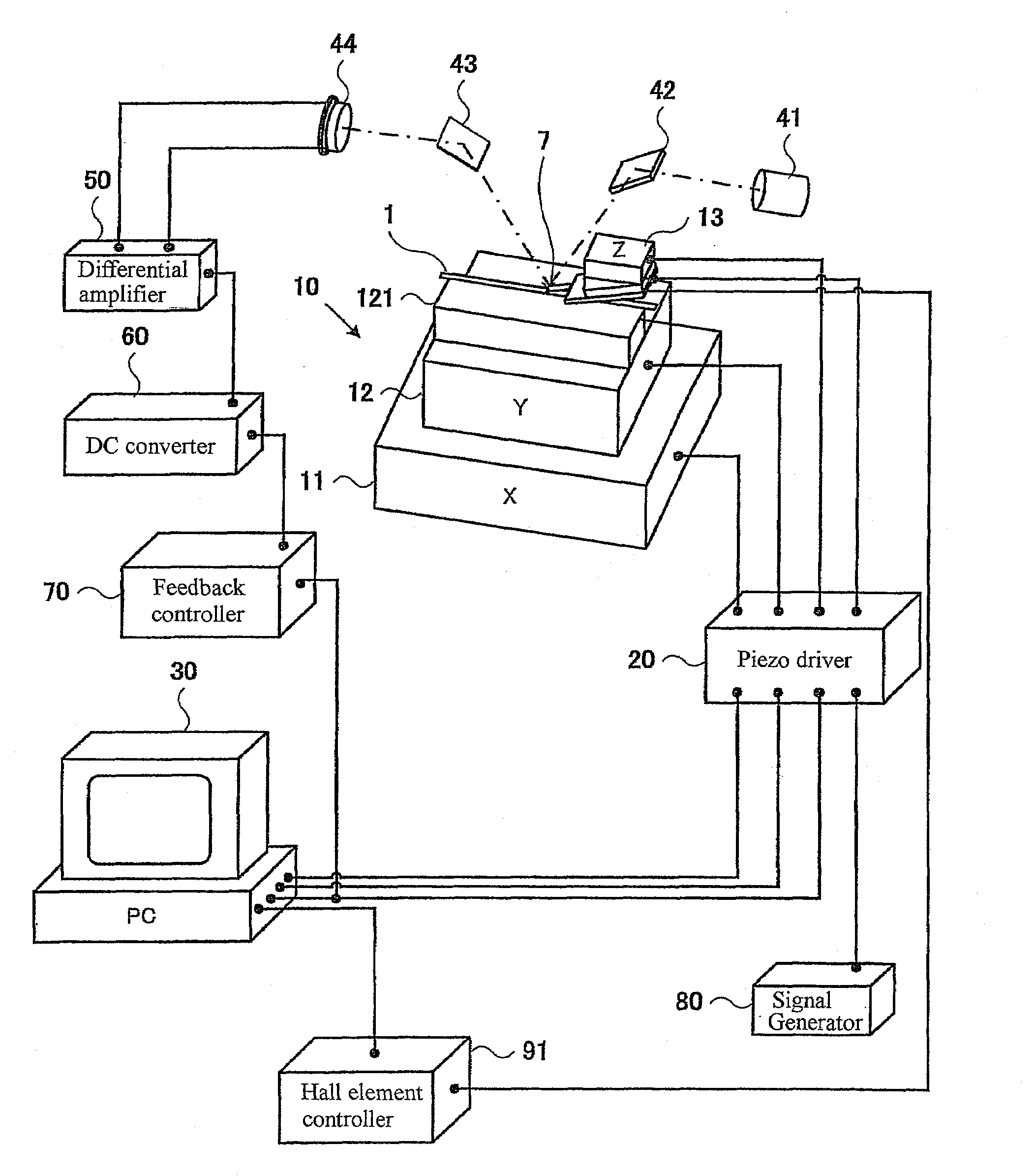
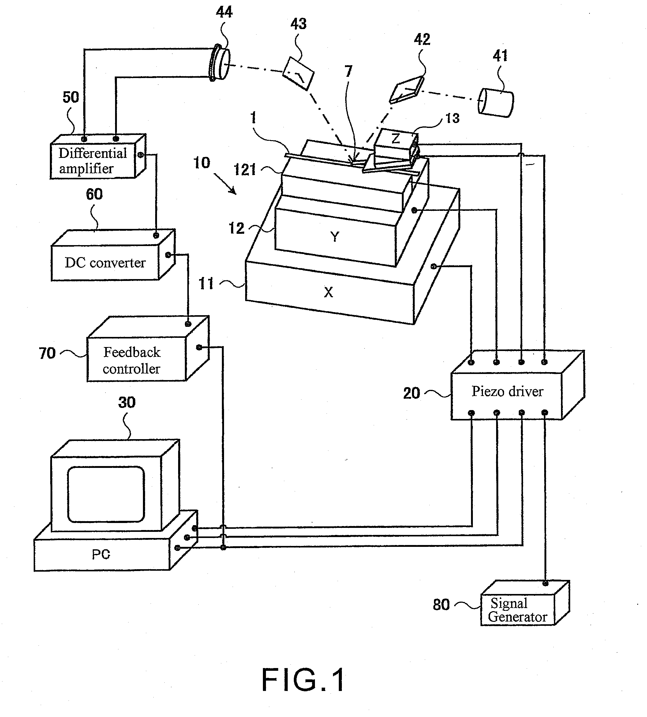
[0024]FIG. 1 is a schematic illustrating the composition of a magnetic head inspection device in one aspect of the present invention. In the magnetic head inspection device in FIG. 1, the effective track width of an MR magnetic head, a giant magneto resistive (GMR) magnetic head, a tunneling magneto resistive (TMR) magnetic head, and the like (referred to as an MR magnetic head below) can be measured in a rowbar state (a block formed by an arrangement of head sliders in block form) prior to the dicing process where the rowbar is separated into individual sliders (or chips).

[0025]Generally, the rowbar is a long and thin block of around 3 cm to 5 cm sliced from a wafer. One rowbar is composed of around 40 to 60 ...


PUM

PropertyMeasurementUnit
Magnetic fieldaaaaaaaaaa
Shapeaaaaaaaaaa
Widthaaaaaaaaaa

Abstract

A magnetic head inspection device inspects the write track width of a thin film magnetic head in a phase as early as possible during the manufacturing process. A recording signal (excitation signal) is input from bonding pads to the thin film magnetic head in a rowbar, and the magnetic field generated by the write pole (element) included in the thin film magnetic head is observed directly by using a magnetic force microscope (MFM), a scanning Hall probe microscope (SHPM), or a scanning magneto resistance effect microscope (SMRM) that performs a scanning motion at a position equivalent to the flying height of the magnetic head. In this manner, a shape of the generated magnetic field instead of the physical shape of the write pole (element) is measured; thus, a non-destructive inspection can be performed on the effective magnetic track width.

Description


Claims


Application Information

Patent Timeline
Owner HITACHI HIGH-TECH CORP
Learn More