Magnetic recording medium, magnetic signal reproduction system and magnetic signal reproduction method

Inactive Publication Date: 2009-07-09
FUJIFILM CORP
View PDF3 Cites 17 Cited by
  • Summary
  • Abstract
  • Description
  • Claims
  • Application Information

AI Technical Summary

Benefits of technology

[0023]The present invention can provide a magnetic recording medium affording good electromagnetic characteristics with highly sensitive MR heads such as highly

Problems solved by technology

When the residual magnetization per unit area of the magnetic layer becomes excessively high, the MR head becomes saturated.
However, these techniques present a problem in that nonmagnetic powder and magnetic powder tend to aggregate, and thus are not necessarily adequate in terms of the uniformity of distribution of magnetic particles in the magnetic layer that is required for noise reduction.
However, none has successfully enhanced the microstructure of the magnetic layer.
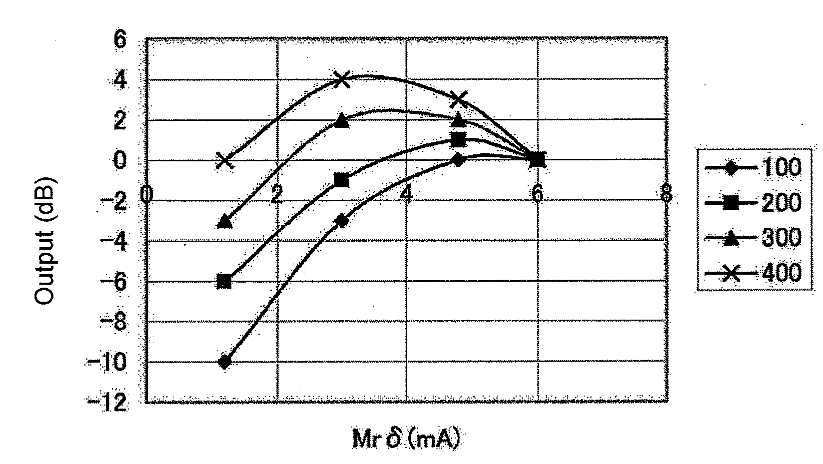
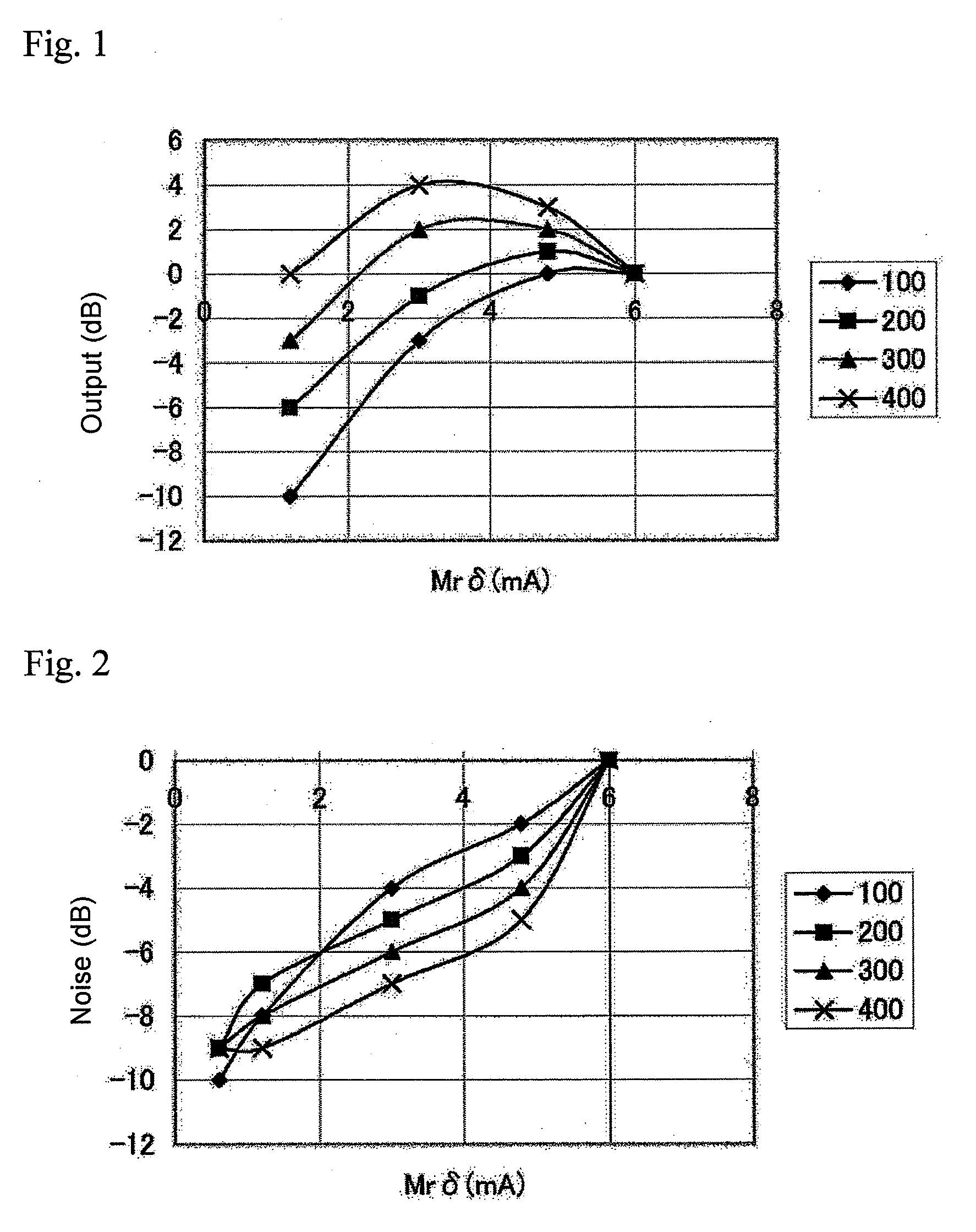
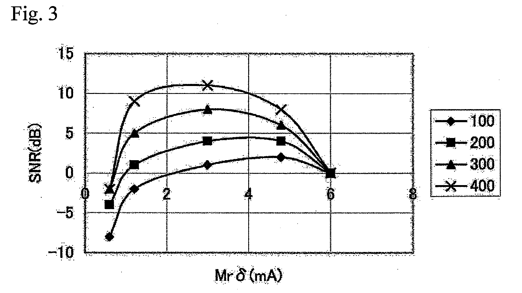
This was thought to occur because when the value of Mrδ was in

Method used


Image

  • Magnetic recording medium, magnetic signal reproduction system and magnetic signal reproduction method
  • Magnetic recording medium, magnetic signal reproduction system and magnetic signal reproduction method
  • Magnetic recording medium, magnetic signal reproduction system and magnetic signal reproduction method

Examples


examples

[0168]The present invention will be described in detail below based on Examples. However, the present invention is not limited to the embodiments described in Examples. The term “parts” given in Examples are mass parts.

examples 1-1 to 1-13

[0169]

Preparation of magnetic layer coating liquid 1(ferromagnetic powder: hexagonal ferrite powder)Ferromagnetic plate-shaped hexagonal ferrite powder100partsComposition other than oxygen (molar ratio):Ba / Fe / Co / Zn = 1 / 9 / 0.2 / 1Hc: 15.9 kA / m (2200 Oe)Plate diameter and plate ratio: see Table 1BET specific surface area: 65 m2 / gσs: 49 A · m2 / kg (49 emu / g)Polyurethane resin based on branched side chain-15partscomprising polyester polyol / diphenylmethanediisocyanate, —SO3Na = 400 eq / tonα-Al2O3 (particle size: 0.15 micrometer)4partsPlate-shaped alumina powder (average particle0.5partdiameter: 50 nm)Diamond powder (average particle diameter: 60 nm)0.5partCarbon black (particle size: 20 nm)1partCyclohexanone110partsMethyl ethyl ketone100partsToluene100partsButyl stearate2partsStearic acid1partPreparation of nonmagnetic layer coating liquidNonmagnetic inorganic powder85partsα-iron oxideSurface treatment agent: Al2O3, SiO2Major axis diameter: 0.15 micrometerTap density: 0.8Acicular ratio: 7BET ...

example 2-1

[0179]With the exception that the magnetic layer coating liquid was changed to magnetic layer coating liquid 2 below, magnetic tape was prepared by the same method as in Example 1-1.

Magnetic layer coating liquid 2 (ferromagneticpowder: iron nitride powder)Iron nitride magnetic powder (average particle100partsdiameter: see Table 2)Hc: 15.9 kA / m (2000 Oe)BET specific surface area: 63 m2 / gσs: 100 A · m2 / kg (100 emu / g)Vinyl chloride-hydroxypropyl acrylate copolymer8partsresin (—SO3Na group content: 0.7 × 10⁻⁴eq / g)Polyurethane resin based on branched side chain-25partscomprising polyester polyol / diphenylmethanediisocyanate, —SO3Na = 400 eq / tonα-alumina (average particle diameter: 80 nm)5partsPlate-shaped alumina powder (average particle1partdiameter: 50 nm)Diamond powder (average particle diameter: 80 nm)1partCarbon black (average particle diameter: 25 nm)1.5partsMyristic acid1.5partsMethyl ethyl ketone133partsToluene100partsStearic acid1.5partsPolyisocyanate (Coronate L made by Nippon P...


PUM


Abstract

The present invention relates to a magnetic recording medium comprising a magnetic layer comprising a ferromagnetic powder and a binder on a nonmagnetic support, wherein the magnetic layer has a thickness δ ranging from 10 to 80 nm, a product, Mrδ, of a residual magnetization Mr of the magnetic layer and the thickness δ of the magnetic layer is equal to or greater than 1 mA but less than 5 mA, a ratio, Sdc/Sac, of an average area Sdc of magnetic clusters in a DC demagnetized state to an average area Sac of magnetic clusters in an AC demagnetized state as measured by a magnetic force microscope, MFM, ranges from 0.8 to 2.0.

Description

CROSS-REFERENCE TO RELATED APPLICATIONS[0001]This application claims the benefit of priority to Japanese Patent Application No. 2006-099940 filed on Mar. 31, 2006, which is expressly incorporated herein by reference in its entirety.TECHNICAL FIELD[0002]The present invention relates to a magnetic recording medium, and more specifically, to a magnetic recording medium suited to ultra-high-density digital recording, affording good electromagnetic characteristics with highly sensitive MR heads such as highly sensitive anisotropic magnetoresistive (AMR) heads and giant magnetoresistive (GMR) heads, particularly a magnetic recording medium suited to reproduction with GMR heads. Still further, the present invention relates to a magnetic signal reproduction method and magnetic signal reproduction system employing the above magnetic reproduction medium.BACKGROUND TECHNIQUE[0003]In recent years, means for rapidly transmitting information at the terabyte level have undergone marked development...

Claims


Application Information

Patent Timeline
IPC IPC(8): G11B5/33
CPCG11B5/70G11B5/714G11B5/70678
Inventor TADA, TOSHIOHARASAWA, TAKESHI
Owner FUJIFILM CORP
Why Eureka
Try Eureka