Power Adapter

a power adapter and power wire technology, applied in the direction of power conversion systems, coupling device connections, electrical apparatus, etc., can solve the problems of limited miniaturization difficult to aim the conducting pieces disposed on the second housing, and occupy a lot of electrical wire space so as to simplify the assembly structure of the power adapter and connect stably to the printed circuit board

Inactive Publication Date: 2010-03-11
CHENG UEI PRECISION IND CO LTD
View PDF3 Cites 18 Cited by
  • Summary
  • Abstract
  • Description
  • Claims
  • Application Information

AI Technical Summary

Benefits of technology

[0009]As described above, by inserting the contact portion of the connecting member into the receiving space of the conductive member, and by connecting the inserting end of the plug module to the retaining portion of the connecting member, the plug module can stably connect to the printed circuit board. Thus, it simplifies the assembly structure of the power adapter.

Problems solved by technology

In this condition, the electric wires take up a lot of space of the power adapter.
It results in the limitation of miniaturizing the power adapter.
However, in the assembly of above mentioned power adapter, it is difficult to aim the conducting pieces disposed on the second housing at the holes defined on the PCB to connect with the second connecting elements of the connector.
As a result, the assembly of the power adapter becomes complicated and the connecting reliability between the plug pins and the PCB will probably be affected.

Method used


Image

  • Power Adapter
  • Power Adapter
  • Power Adapter

Examples


Embodiment Construction

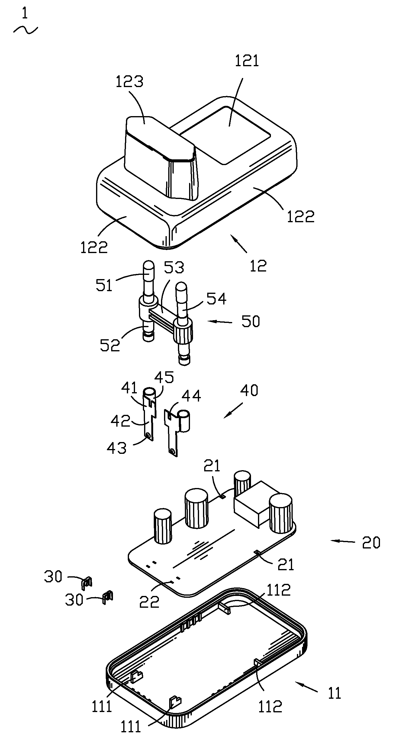
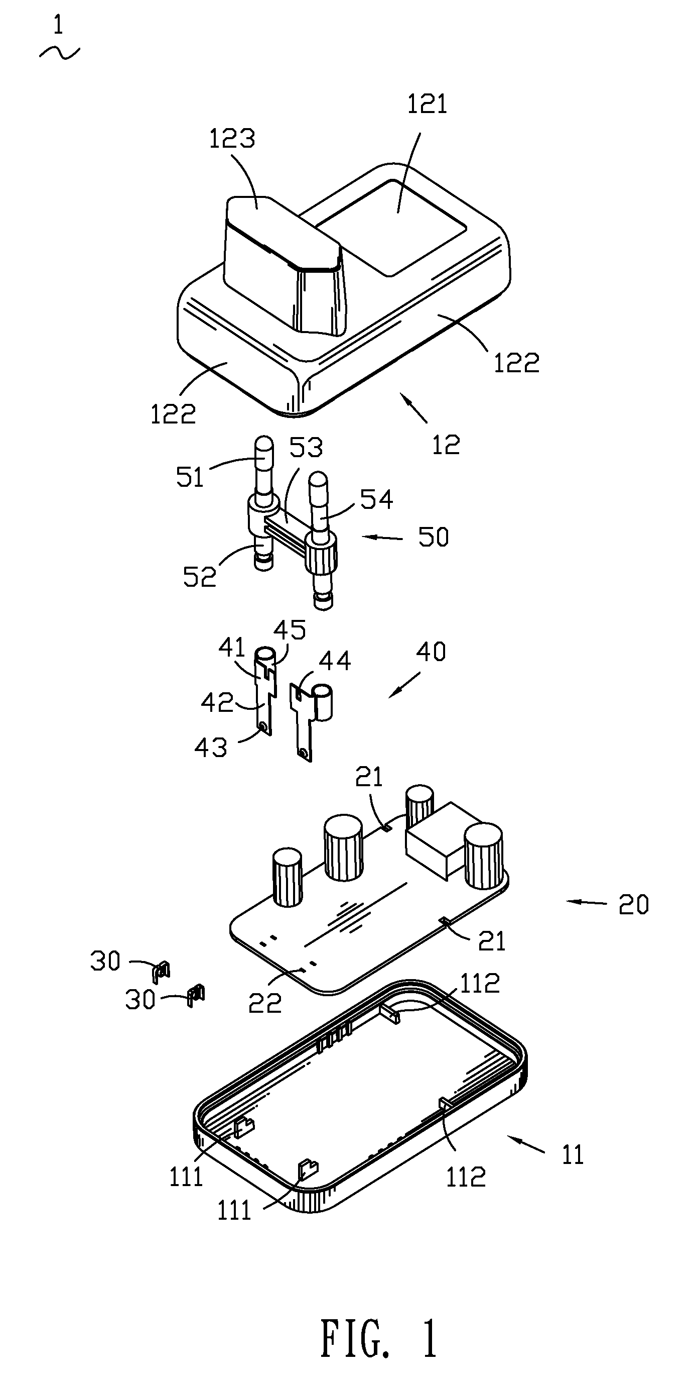
[0019]Referring to FIG. 1 to FIG. 5 showing a first preferred embodiment of a power adapter 1 in accordance with the present invention, the power adapter 1 includes a first insulation casing 11 and a second insulation casing 12 coupled to the first insulation casing 11 to form a closed space to receive a printed circuit board (PCB) 20, a pair of conductive members 30, a pair of connecting members 40 and a plug module 50 therein.

[0020]The first insulation casing 11 defines a pair of first holders 111 in substantial L-shape on a bottom thereof. The bottom of the first insulation casing 11 defines a pair of first ribs 112 respectively connecting with two opposite sides of the first insulation casing 11.

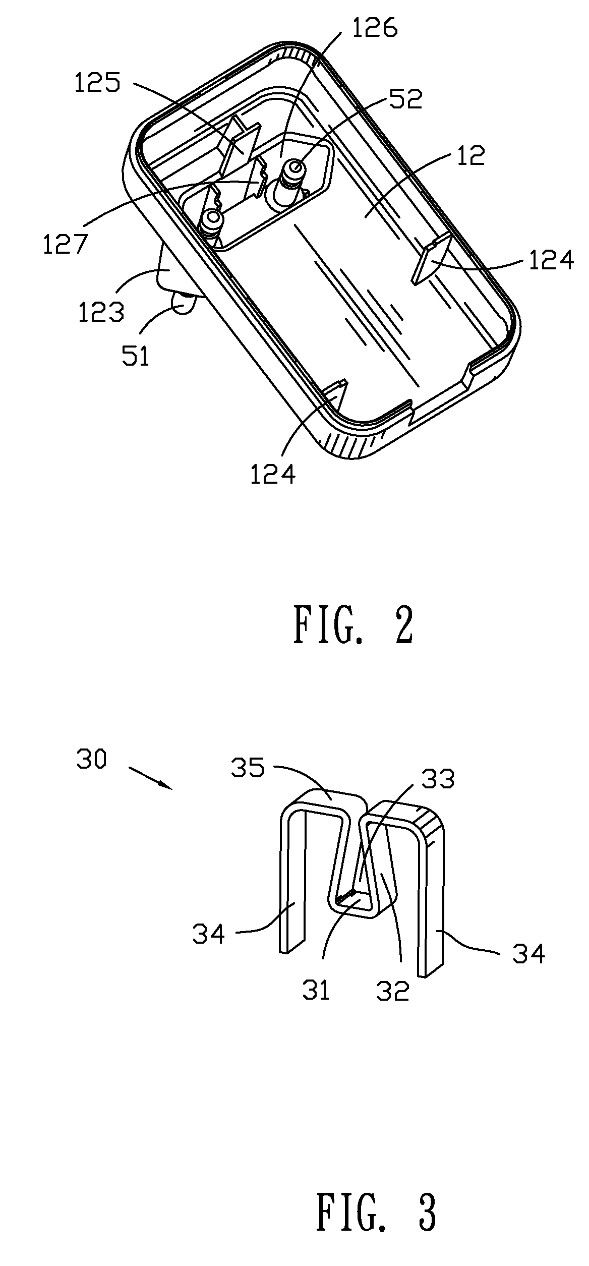
[0021]Referring to FIG. 1 and FIG. 2, the second insulation casing 12 has a top wall 121, sidewalls 122 extending downward from corresponding sides of the top wall 121, and a convex portion 123 having a notch 126 therein protruding upwardly from an outer surface of the top wall 121. Corr...


PUM


Abstract

A power adapter includes an insulation casing. A plug module has at least one plug pin which defines a plug end protruding out of the insulation casing and an inserting end opposite to the plug end received in the insulation casing. The insulation casing receives a printed circuit board, at least one connecting member and conductive member therein. The conductive member is fixed on the printed circuit board and defines a receiving space. The connecting member has a contact portion received in the receiving space of the conductive member for electrical connection therebetween and a retaining portion connecting with the inserting end of the plug module. The assembly structure of the power adapter is simplification.

Description

BACKGROUND OF THE INVENTION[0001]1. Field of the Invention[0002]The present invention generally relates to a power adapter, and more particularly to a power adapter capable of stably connecting a plug module with a printed circuit board thereof.[0003]2. The Related Art[0004]A conventional power adapter includes an insulation casing, plugs, a printed circuit board (PCB) and electric wires. The insulation casing includes a first insulation casing and a second insulation casing coupled to the first insulation casing to form a closed space to receive the PCB and the electric wires therein. The plugs are exposed out of the first insulation casing. The electric wires are used to connect the plugs with the PCB, and thereby the PCB can receive external power via the plugs and the electric wires to perform functions of the power adapter.[0005]Nowadays, that various electronic devices including the power adapters are miniaturized becomes a tendency. However, because the conventional power ada...

Claims


Application Information

Patent Timeline
Patent Type & Authority Applications(United States)
IPC IPC(8): H02M1/00
CPCH01R13/6675H01R12/718H01R31/065
Inventor ZHANG, YONGLIAO, YONG-JUNTANG, GUO-QIANG
Owner CHENG UEI PRECISION IND CO LTD
Why Eureka
Try Eureka