Engine mount of vehicle

a technology for engine mounts and vehicles, applied in the direction of machine supports, shock absorbers, jet propulsion mountings, etc., can solve the problems of complex assembly structure and insufficient fixation of engine mounts, and achieve the effects of preventing water, preventing corrosion of housings and brackets, and improving durability

Active Publication Date: 2011-06-09
HYUNDAI MOTOR CO LTD +1
View PDF5 Cites 16 Cited by
  • Summary
  • Abstract
  • Description
  • Claims
  • Application Information

AI Technical Summary

Benefits of technology

[0028]First, since the engine mount is combined in a cocking way by the insertion grooves formed in the housing and the protrusions formed in the inner case, it is possible to firmly fix the engine mount by preventing it from easily separated by an external shock, such as a collision of vehicles.
[0029]Second, since the engine mount is further combined by the curling portion at the lower portion of the housing, in addition to the cocking combination by the insertion grooves and the protrusions, it is possible more firmly fix the engine mount and preclude corrosion of the housing and brackets by preventing water etc. from flowing into the curling portion of the housing.
[0030]Third, since the ring plate and the diaphragm are integrally attached to the lower portion of the body, water or pollutants are basically prevented from flowing into lower portion of the ring plate, thereby improving durability.

Problems solved by technology

H08-226487 has a structure in which only one sheet is pressed to the lower end of the main body plate, such that it is vulnerable to an external shock, such as a collision of vehicles, and the engine mount is not sufficiently fixed.
However, the invention disclosed in Japanese Patent Application Laid-Open No. 2004-293607 requires many components for assembling the engine mount, such as the first fitting device, the second fitting device, the cocking portion, and the circular fitting device, such that the assembly structure is complicated.

Method used


Image

  • Engine mount of vehicle
  • Engine mount of vehicle
  • Engine mount of vehicle

Examples


Embodiment Construction

[0037]Reference will now be made in detail to various embodiments of the present invention(s), examples of which are illustrated in the accompanying drawings and described below. While the invention(s) will be described in conjunction with exemplary embodiments, it will be understood that present description is not intended to limit the invention(s) to those exemplary embodiments. On the contrary, the invention(s) is / are intended to cover not only the exemplary embodiments, but also various alternatives, modifications, equivalents and other embodiments, which may be included within the spirit and scope of the invention as defined by the appended claims.

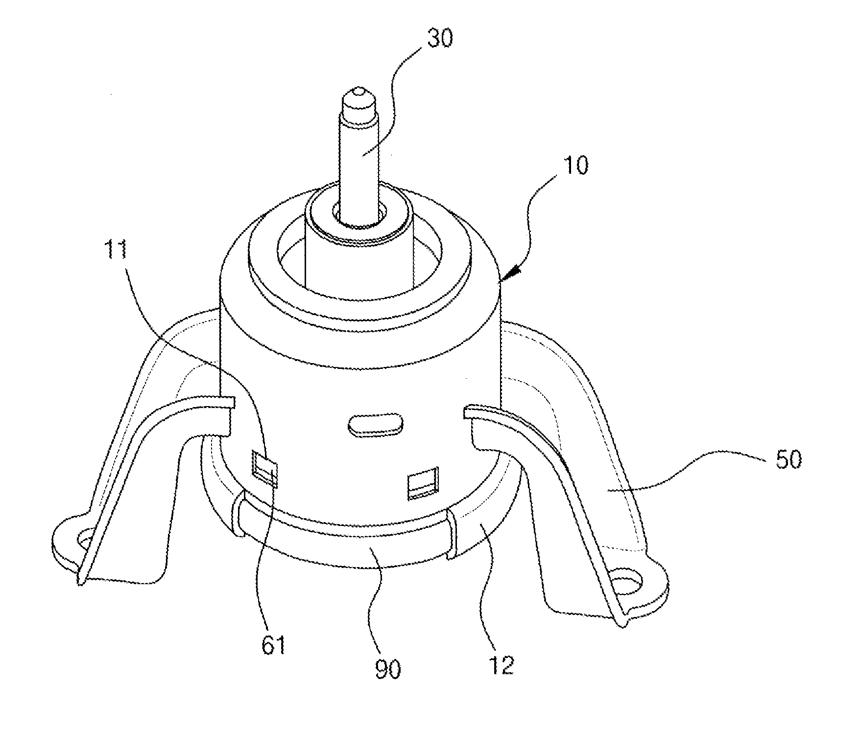
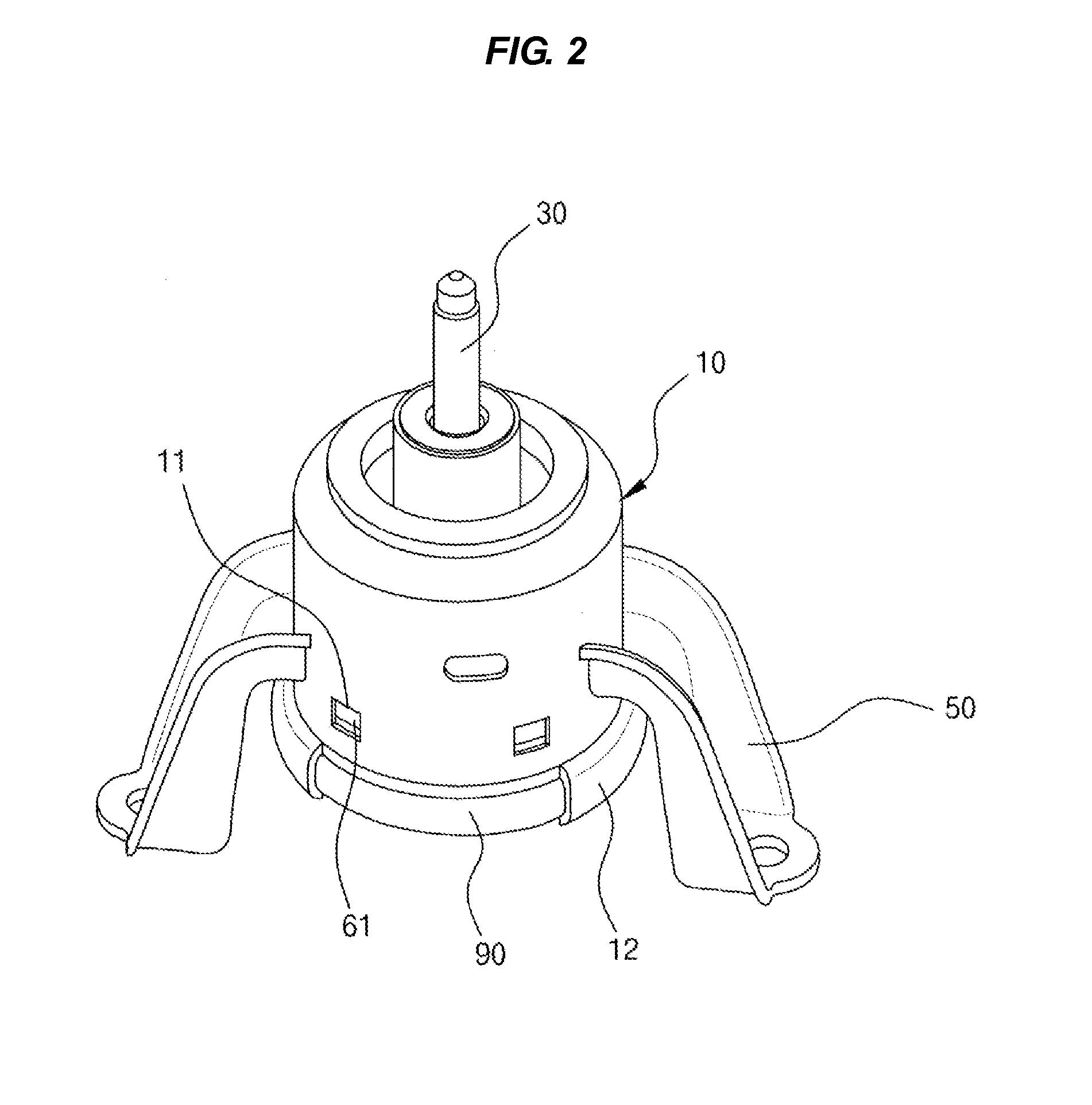
[0038]The configuration of an engine mount according to an exemplary embodiment of the present invention is described in detail with the accompanying drawings.

[0039]It should be understood, however, that the given drawings are provided as examples for sufficiently communicating the spirit of the present invention to those skilled in t...


PUM


Abstract

An engine mount of a vehicle may include a main rubber body defining a main liquid chamber, wherein a fastening bolt for assembling a vehicle engine is coupled to the main rubber body, an inner case supporting the main rubber body, and a housing enclosing the main rubber and the inner case, wherein at least a protrusion is formed on an outer circumference of the inner case, and wherein at least a groove is formed in the housing and the at least a protrusion of the inner case is coupled to the corresponding at least a groove of the housing.

Description

[0001]The present application claims priority to Korean Patent Application No. 10-2009-0119758, filed on Dec. 4, 2009, the entire contents of which is incorporated herein for all purposes by this reference.BACKGROUND OF THE INVENTION[0002]1. Field of the Invention[0003]The present invention relates to an engine mount of a vehicle which reduces vibration generated by the operation of an engine, in more detail, an engine mount of a vehicle including a main rubber body in which a fastening bolt for assembling a vehicle engine is inserted, an inner case supporting the main rubber body and combined with the main rubber body, and a housing connected to the outer side of the inner case and defining the external appearance of the engine mount, in which at least one or more protrusions are formed on the outer circumference of the inner case, at least one or more insertion grooves where the protrusions are inserted are formed in the housing, and the protrusions of the inner case are inserted ...

Claims


Application Information

Patent Timeline
Patent Type & Authority Applications(United States)
IPC IPC(8): F16F13/14B60K5/12
CPCF16F13/108F16F13/103B60K5/12B60K5/00
Inventor HWANG, JI-SOORYU, GYEONG-MIN
Owner HYUNDAI MOTOR CO LTD
Why Eureka
Try Eureka