Pressure sensor

a pressure sensor and sensor technology, applied in the field of pressure sensors, can solve the problems of reducing the number of assembly processes or failing to consider improving the air tightness, and achieve the effects of improving the assembling characteristics, improving the air tightness, and simplifying the structure of the assembled pressure sensor

Inactive Publication Date: 2005-01-20
FUJIKOKI CORP
View PDF1 Cites 15 Cited by
  • Summary
  • Abstract
  • Description
  • Claims
  • Application Information

AI Technical Summary

Benefits of technology

[0009] The present invention provides a pressure sensor having increased airtightness, and since the pressure sensor comprises as its main components a holder, a connector case, a diaphragm and a lid member, the structure of the assembled pressure sensor can be simplified. Furthermore, since the diaphragm is sandwiched between the holder and the lid member, the pressure sensor has improved assembling characteristics.

Problems solved by technology

The prior art pressure sensing elements and semiconductor pressure sensors having the signal processing circuit disposed within the filled fluid fail to consider improving the airtightness or reducing the number of assembly processes.

Method used


Image

  • Pressure sensor
  • Pressure sensor
  • Pressure sensor

Examples


embodiment 1

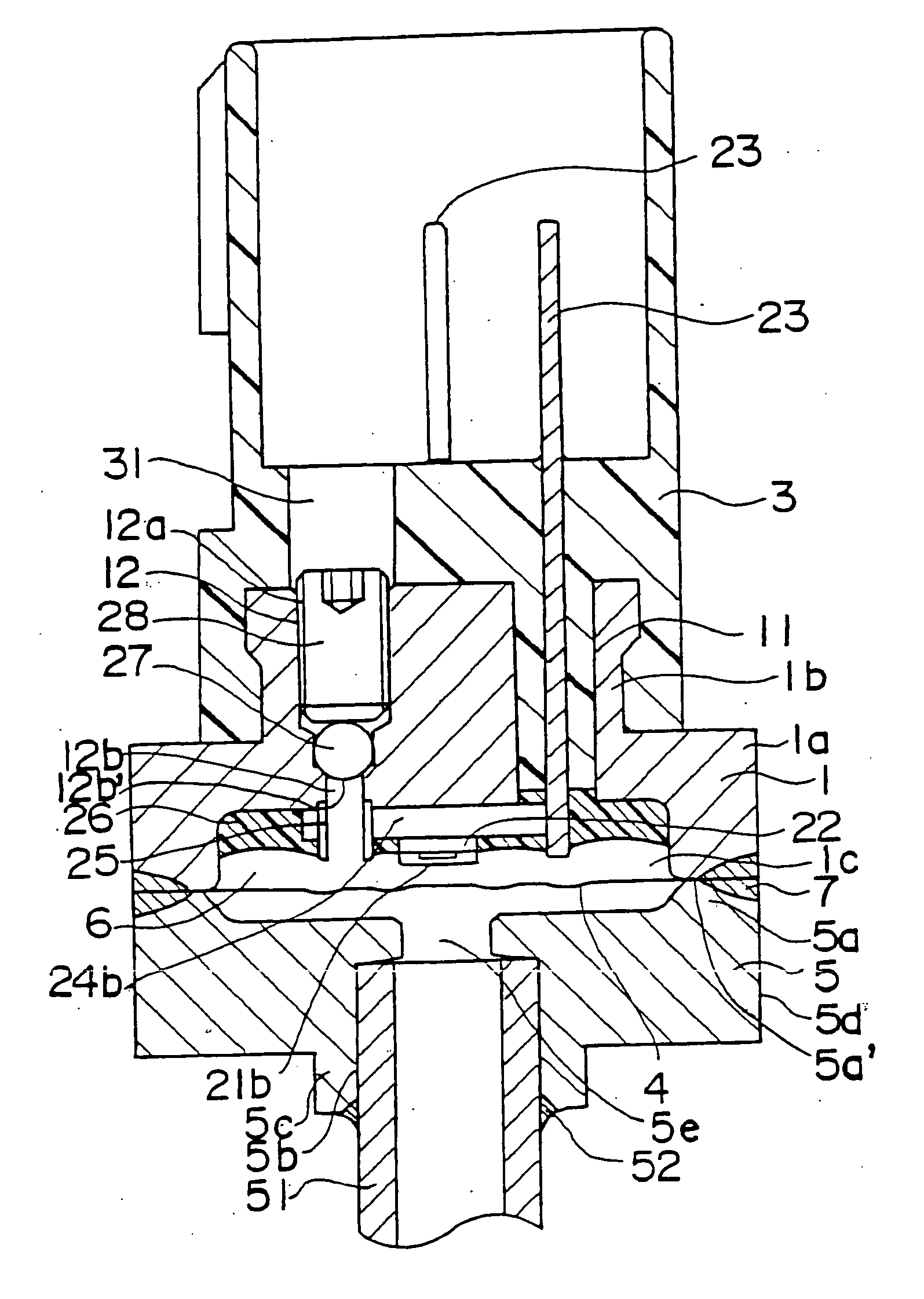
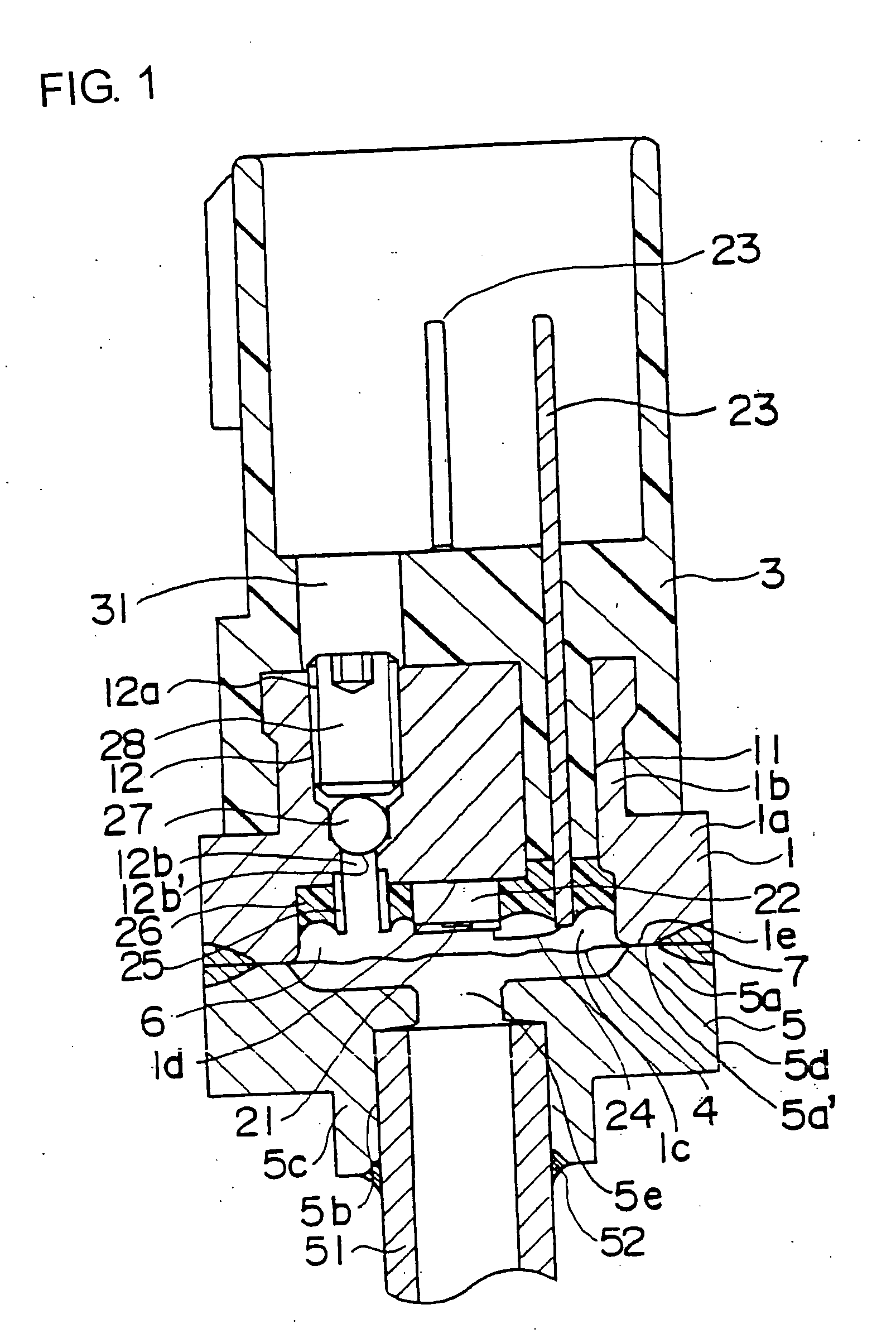
[0013] The first embodiment of the pressure sensor according to the present invention will be explained. As shown in FIG. 1, the pressure sensor according to the present embodiment comprises a holder 1, a connector case 3, a diaphragm 4 and a lid member 5.

[0014] The holder 1 is made of metal such as stainless steel, and comprises a disk-shaped base portion la and a cylindrical column portion 1b formed integrally to the inner side of the base portion and defining in its interior a space that functions as a pressure sensing chamber 6. To the column portion 1b are formed a through-hole 12 having a large-diameter portion 12a and a small-diameter portion 12b, and an outlet 11 in which a lead member 23 is disposed, both of which are formed vertically to the housing, that is, perpendicular to the diaphragm 4. In the through-hole 12, a first seal member 27 and a second seal member 28 are disposed. The small-diameter portion 12b of the through-hole 12 is communicated with the pressure sensi...

embodiment 2

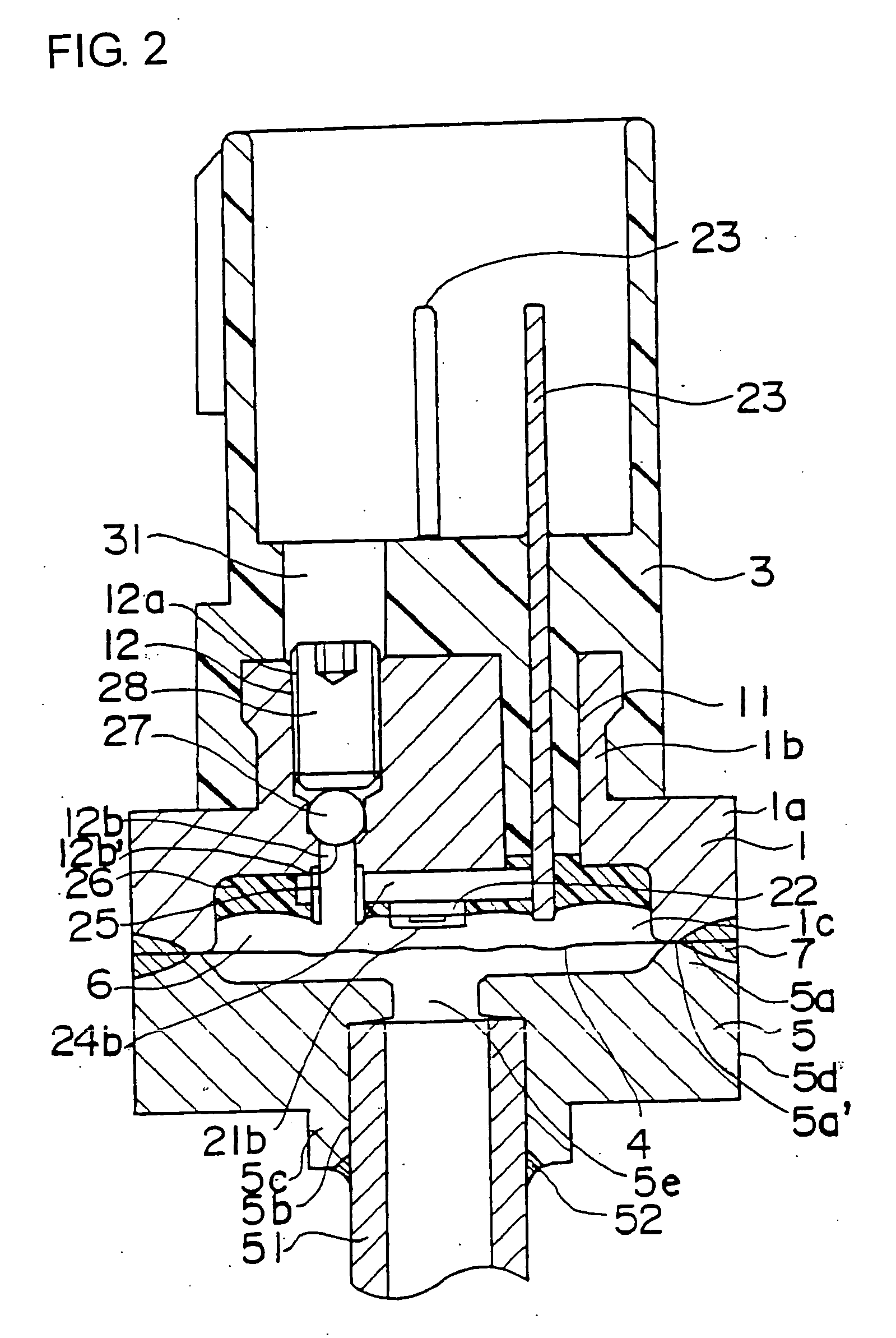
[0030] Now, the second embodiment of the pressure sensor according to the present invention will be explained. According to the present embodiment, the structure of the semiconductor pressure sensor element differs from that of the first embodiment, and as shown in FIG. 2, the semiconductor pressure sensor element 21b constituting a bridge circuit is mounted on a substrate 24b via a seat 22. The semiconductor pressure sensor element 21b detects pressure and generates a voltage signal, and the substrate 24b that constitutes a circuit unit for processing the voltage signal is fixed onto the lower surface of the holder 1 within the pressure sensor chamber 6. The circuit unit is electrically connected to the semiconductor pressure sensor element 21b, and the lead member 23 is electrically connected to the substrate 24b. Moreover, the surface of substrate 24b is covered with an adhesive or resin seal 26. The other structures are similar to that of embodiment 1 shown in FIG. 1, so the ide...


PUM

PropertyMeasurementUnit
pressureaaaaaaaaaa
structureaaaaaaaaaa
diameteraaaaaaaaaa

Abstract

A pressure sensor comprising a holder 1 having mounted thereto a semiconductor pressure sensor element 2 that outputs a voltage signal corresponding to the pressure it receives, a connector case 3 for fixing a lead member 23 connected to the semiconductor pressure sensor element 21, a diaphragm 4 that defines together with the holder 1 a pressure sensing chamber 6 filled with insulating oil, and a lid member 5 made of metal to which a pressure introduction pipe 51 is mounted, wherein the holder 1 is made of metal and has a through-hole 12 that communicates the pressure sensing chamber 6 with the exterior and a seal member 27 that seals the through-hole 12, the connector case 3 has an insert hole 31 communicated with the through-hole 12 and through which the seal member 27 is inserted, and the diaphragm 4 is sandwiched between the holder 1 made of metal and the lid member 5 made of metal and bonded thereto.

Description

FIELD OF THE INVENTION [0001] The present invention relates to a pressure sensor, and specifically, relates to a pressure sensor comprising a holder, connector case, diaphragm and lid member, and having a fluid filled in a pressure sensing chamber storing a pressure sensing element. DESCRIPTION OF THE RELATED ART [0002] Heretofore, various types of semiconductor pressure sensors have been proposed according to which a fluid is filled in a pressure sensing chamber storing the semiconductor pressure sensor element and pressure from the exterior is transmitted to the semiconductor pressure sensor element stored in the pressure sensing chamber via the fluid, and the pressure sensor element outputs a voltage signal corresponding to the pressure it receives (refer to Patent Document 1). [0003] Further, Patent Document 2 discloses a semiconductor pressure sensor comprising a sensor having circuit elements of a strain gage and a signal processing circuit integrated on a semiconductor elemen...

Claims


Application Information

Patent Timeline
Patent Type & Authority Applications(United States)
IPC IPC(8): G01L19/14G01L9/00G01L9/06H01H35/34H01L29/84
CPCG01L19/142G01L19/0645G01L9/06H01H35/34
Inventor SASAKI, KEIJINAGASE, HITOSHI
Owner FUJIKOKI CORP
Why Eureka
Try Eureka