
Method and device for ammonia storage and delivery using in situ re-saturation of a delivery unit

a technology of ammonia storage and resaturation, which is applied in the direction of non-pressured vessels, containers discharging from non-pressured vessels, internal combustion piston engines, etc., can solve the problems of less safety and high ammonia pressure in storage containers

Inactive Publication Date: 2010-03-11
AMMINEX
View PDF17 Cites 37 Cited by
  • Summary
  • Abstract
  • Description
  • Claims
  • Application Information

AI Technical Summary

Benefits of technology

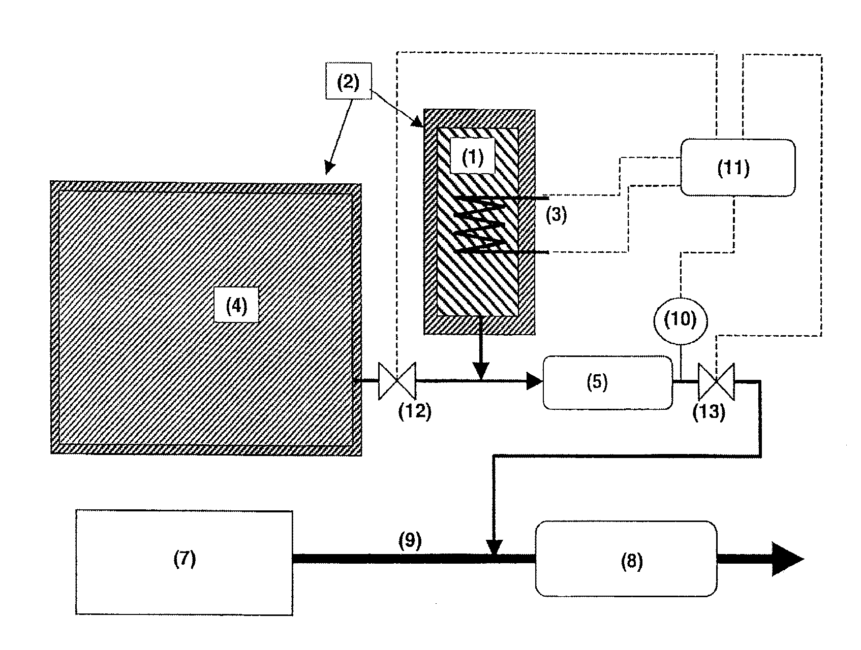
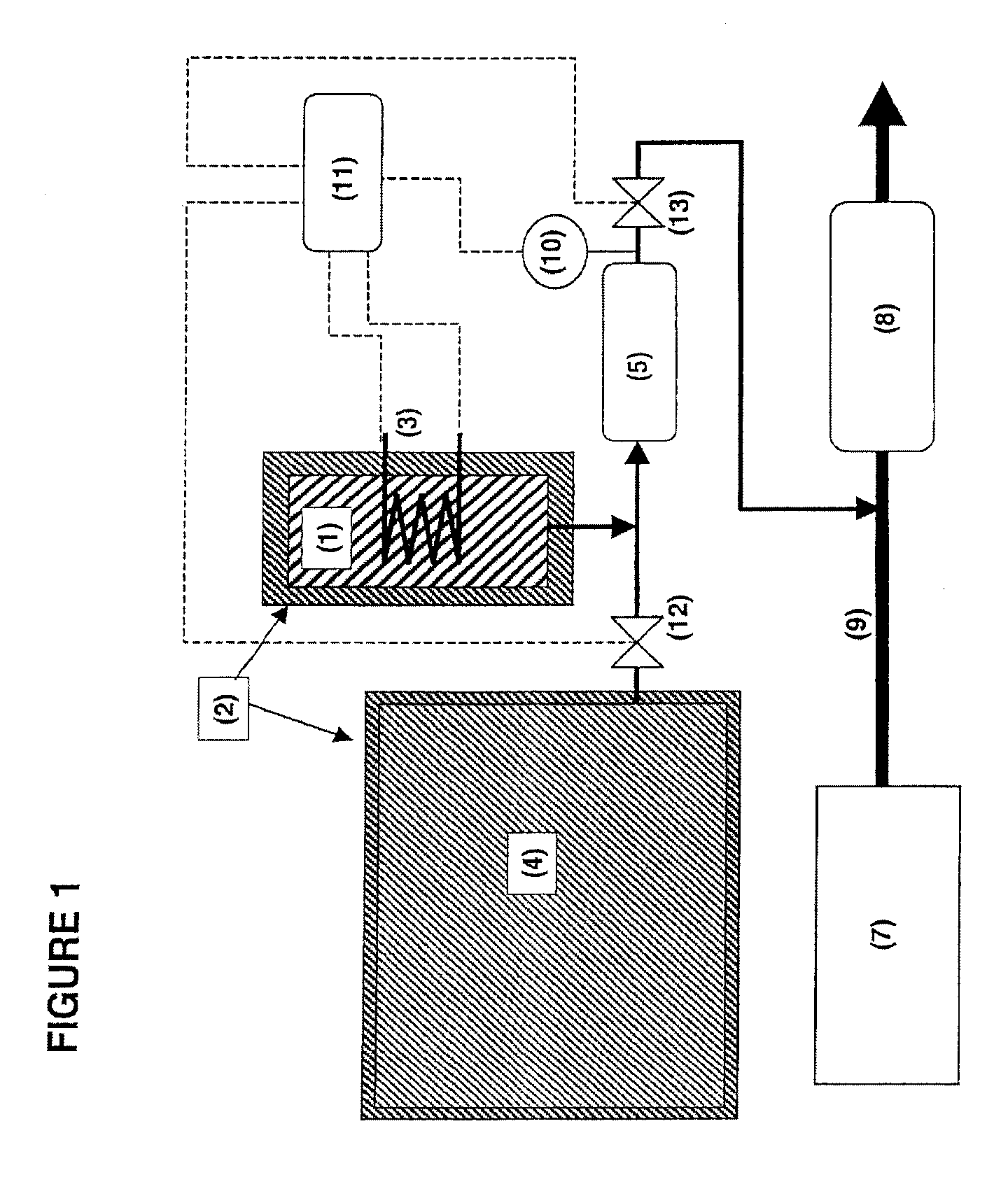
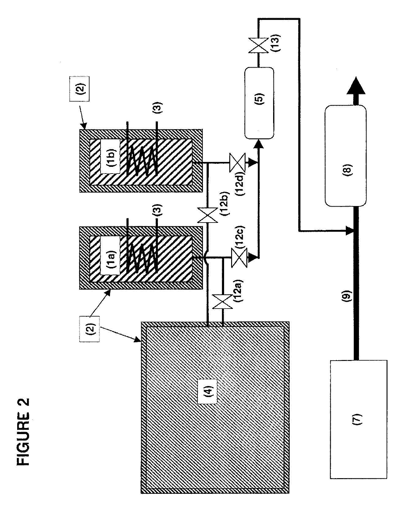
[0026]The invention also relates to systems and other devices and methods using the principle of this invention. These systems and other devices and methods may utilize the storage and release concept for various processes requiring ammonia. Such devices or systems can include NOx reduction in exhaust gases from combustion processes or engines. It may also include fuel cells operating on ammonia generated from a storage device or system or on hydrogen that may be generated from catalytic cracking of ammonia.
[0027]The invention also relates to a method of using the principle of passive regeneration of an ammonia releasing unit with a larger container containing a more volatile ammonia storing material. Partial or full degassing of a smaller unit is reversed by ammonia migration from the larger container to the smaller unit.

Problems solved by technology

However, the use of the ammonia storage media known from WO 99 / 01205 suffers from various draw-backs hampering a wide-spread use in the automotive industry.
This is not a problem by itself, but the material is rather volatile and in the case that the control of the heating fails one can reach a situation of over-heating and thus reach very high ammonia pressures in a storage container—even at temperatures below 100° C.
Other ammonia adsorbing / absorbing materials have similar problems in that they are either safe, since they have a low ammonia pressure, but require comparatively much energy for ammonia desorption, or require less energy for ammonia desorption, but are less safe, because high ammonia pressures may be built up.

Method used


Image

  • Method and device for ammonia storage and delivery using in situ re-saturation of a delivery unit
  • Method and device for ammonia storage and delivery using in situ re-saturation of a delivery unit
  • Method and device for ammonia storage and delivery using in situ re-saturation of a delivery unit

Examples


Embodiment Construction

[0030]The present invention is related to a method, device and system for ammonia storage and delivery that can e.g. be used for on-board storage and a delivery system for e.g. DeNOx by selective catalytic reduction using ammonia as the reductant. It may be used for other purposes requiring controlled dosing / delivery of ammonia from a compact storage unit.

[0031]One aspect of the invention is a method for storing and delivering ammonia, wherein a first ammonia adsorbing / absorbing material having a higher vapor pressure at a given temperature than a second ammonia adsorbing / absorbing material is used as an ammonia source for said second ammonia adsorbing / absorbing material when said second adsorbing / absorbing material is depleted of ammonia.

[0032]Another aspect of the invention is device for ammonia storage and delivery where the storage capacity is divided into at least two containers or compartments with said containers or compartments containing different ammonia absorbing material...


PUM

PropertyMeasurementUnit
pressureaaaaaaaaaa
pressureaaaaaaaaaa
ammonia vapour pressureaaaaaaaaaa

Abstract

Disclosed is a method for storing and delivering ammonia, wherein a first ammonia adsorbing / absorbing material having a higher vapor pressure at a given temperature than a second ammonia adsorbing / absorbing material is used as an ammonia source for said second ammonia adsorbing / absorbing material when said second adsorbing / absorbing material is depleted of ammonia by consumption, and a device for performing the method.

Description

BACKGROUND OF THE INVENTION[0001]1. Field of the Invention[0002]This invention relates to a method and device for storing and generating of ammonia from storage materials capable of binding and releasing ammonia reversibly. In particular, the storage materials are solid metal ammine complexes capable of binding and releasing ammonia reversibly. The method and device may be used in the selective catalytic reduction of NOx.[0003]Other applications using ammonia in mobile or portable units or in special chemical synthesis routes where storage of liquid ammonia is too hazardous are also contemplated embodiments of the present invention. This also includes fuel cell systems where ammonia may be considered an efficient hydrogen carrier.[0004]2. Description of the Related Art[0005]As disclosed in applicant's co-pending application (WO2006012903) metal ammine salts can be used as a solid storage media for ammonia which in turn may be used as the reductant in selective catalytic reduction to...

Claims


Application Information

Patent Timeline
Patent Type & Authority Applications(United States)
IPC IPC(8): B01D53/94F01N3/20F17C9/00F17C11/00H01M8/18
CPCB01D53/02Y02T10/24B01D53/8625B01D53/90B01D53/9409B01D53/9431B01D2251/2062B01D2253/10B01D2253/20B01D2257/406B01D2259/4525C01C1/006C01C1/02F01N3/2066F01N2610/02F01N2610/06F01N2610/10F01N2610/11F01N2610/14F01N2610/1406H01M8/04208H01M8/04216H01M8/0606H01M8/222H01M2008/1293Y02E60/50Y02E60/525B01D53/0407F17C11/00Y02A50/20Y02P20/50Y02T10/12
Inventor JOHANNESSEN, TUE
Owner AMMINEX
Learn More