Process for Urea Production and Related Plant

a technology of urea and process, applied in the field of process for urea production, to achieve the effects of high conversion yield, low energy consumption, and high production capacity of the plan

Active Publication Date: 2010-03-11
CASALE SA
View PDF7 Cites 8 Cited by
  • Summary
  • Abstract
  • Description
  • Claims
  • Application Information

AI Technical Summary

Benefits of technology

The technical problem of this patent is to develop a process for urea production that can achieve high production capacity and conversion yield of carbon dioxide to urea with low energy consumption. This process aims to overcome the drawbacks of prior art methods.

Problems solved by technology

The technical problem addressed in this patent is the need to increase the capacity of urea production plants without compromising the conversion yield and energy efficiency of the process.

Method used


Image

  • Process for Urea Production and Related Plant
  • Process for Urea Production and Related Plant
  • Process for Urea Production and Related Plant

Examples


Embodiment Construction

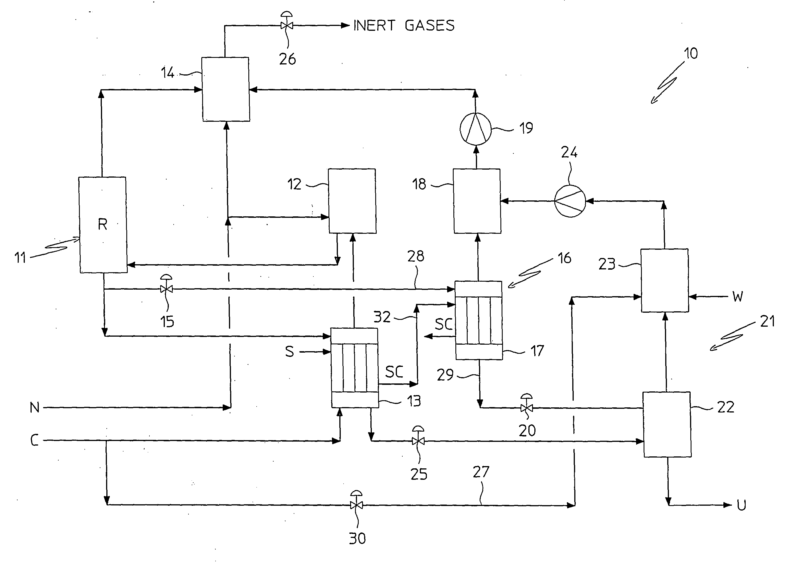
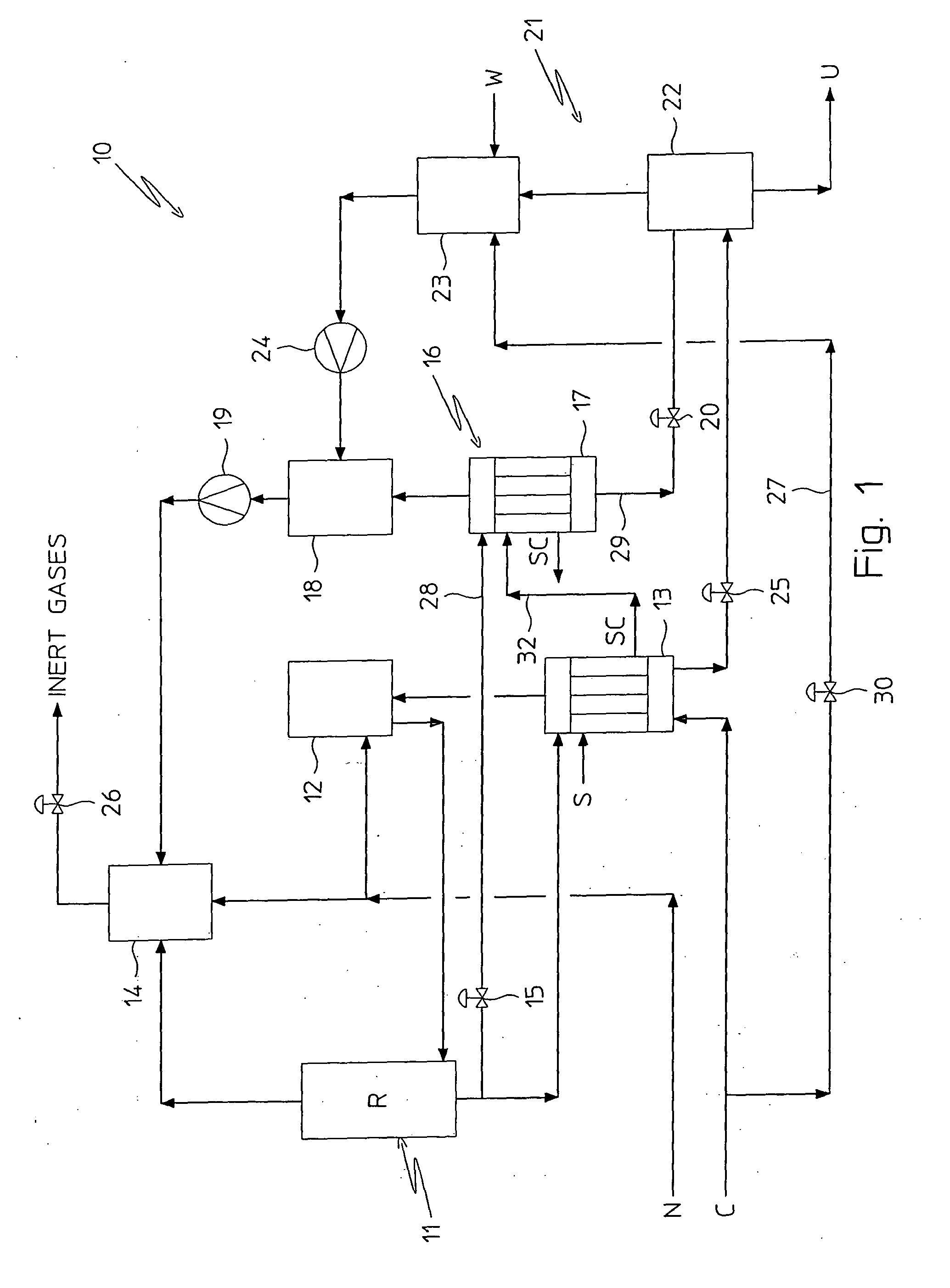
[0060]With reference to FIG. 1, a plant, wholly indicated with 10, for urea production is shown, which carries out the process according to an embodiment of the present invention.

[0061]According to the aforementioned process for urea production, ammonia N and carbon dioxide C are fed into an appropriate synthesis section 11. In the example of FIG. 1, the urea synthesis section comprises a single reactor R.

[0062]In particular, according to such an example, the ammonia N is fed to the reactor R through a condenser 12 and the carbon dioxide C is in turn fed to the reactor R through a stripper 13 and the condenser 12.

[0063]The synthesis section 11 (reactor R), the condensation unit (condenser 12), the stripping unit (stripper 13), together with a scrubber 14 (that shall be described hereafter in greater detail), all operate substantially at the same high pressure, thus constituting the high pressure synthesis loop (H.P. Loop) of the process of the present invention.

[0064]In the reactor ...


PUM


Abstract

A process for urea production from ammonia and carbon dioxide, in which part of the aqueous solution comprising urea, ammonium carbamate and ammonia obtained in a urea synthesis section is subjected to dissociation in a treatment section operating at a predetermined medium pressure for the recovery of the ammonium carbamate and of the ammonia contained in it, comprises the steps of subjecting the urea aqueous solution resulting from the aforementioned dissociation step to decomposition in a low pressure urea recovery section and of using at least a part of the condensed steam, obtained by indirect thermal exchange with a second part of said aqueous solution comprising urea, ammonium carbmate and ammonia in a high-pressure stripping unit, as a heating fluid for the dissociation of the first part of the aqueous solution comprising urea, ammonium carbmate and ammonia in the medium-pressure treatment section.

Description


Claims


Application Information

Patent Timeline
Owner CASALE SA
Why Eureka
Try Eureka