
Electrosurgical Apparatus With High Speed Energy Recovery

a high-speed, energy-recovery technology, applied in the field of electrosurgical generators, can solve problems such as impedance levels and potential patient burn hazards

Active Publication Date: 2010-03-11
TYCO HEALTHCARE GRP LP
View PDF5 Cites 42 Cited by
  • Summary
  • Abstract
  • Description
  • Claims
  • Application Information

AI Technical Summary

Benefits of technology

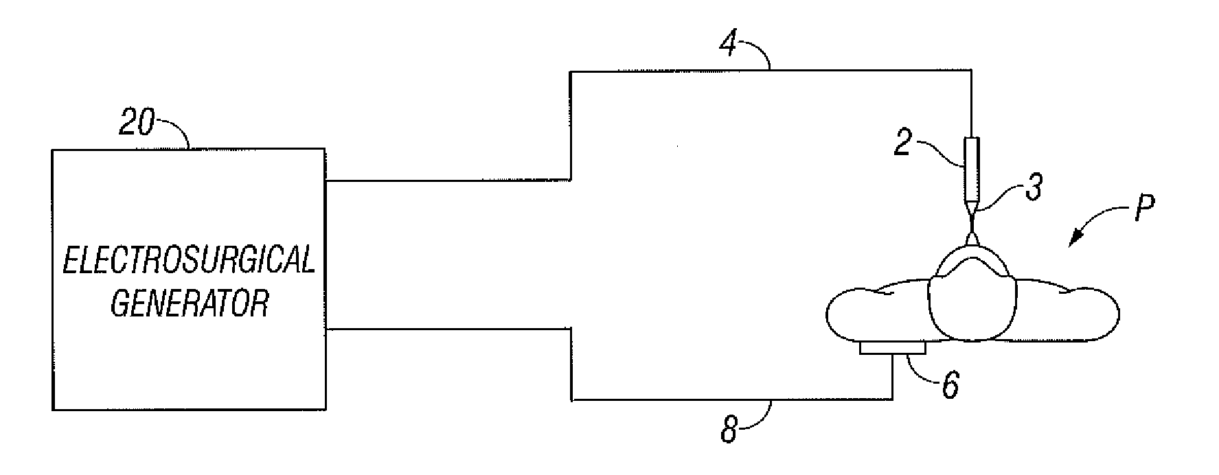
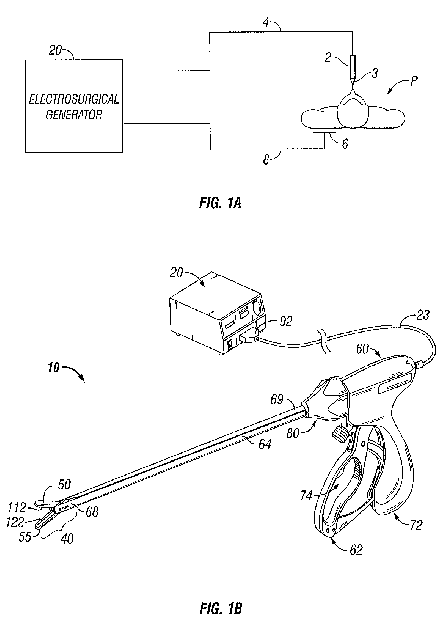
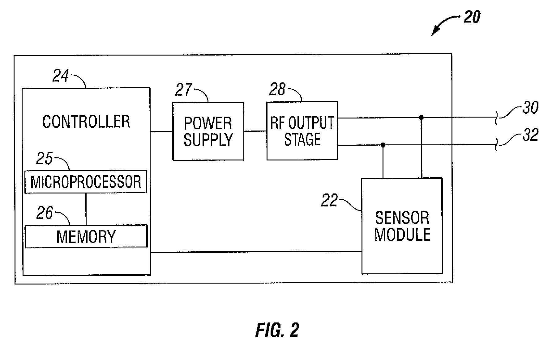
[0007]According to one embodiment of the present disclosure, a circuit for controlling the discharging of stored energy in an electrosurgical generator includes a pulse modulator which controls an output of a power supply. At least one comparator is configured to provide an error signal to the pulse modulator based on a comparison between an output generated by the power supply and a feedback signal generated in response to the application of energy to tissue. A discharge circuit is configured to control the discharge of the output of the power supply to an inductive load disposed in parallel with the output of the power supply based on the comparison between the power supply output and the feedback signal.
[0008]According to another embodiment of the present disclosure, a circuit for controlling the discharging of stored energy in an electrosurgical generator includes a pulse modulator which controls an output of a power supply. At least one comparator is configured to provide an error signal to the pulse modulator based on a comparison between an output generated by the power supply and a feedback signal generated in response to the application of energy to tissu...

Problems solved by technology

Rapid tissue desiccation during the application of RF energy creates a potential for patient burn hazards due to excess energy dosage at the tissue site when the power source fails to rapidly alter the supplied energy dosage in response with dynamic changes in tissue impedance.
Rising tissue impedance levels caused by desiccation unload the energy source and sustain the energy delivered to the tissue due to the large amount of stored energy in the output filter.

Method used


Image

  • Electrosurgical Apparatus With High Speed Energy Recovery
  • Electrosurgical Apparatus With High Speed Energy Recovery
  • Electrosurgical Apparatus With High Speed Energy Recovery

Examples


Embodiment Construction

[0016]Particular embodiments of the present disclosure are described hereinbelow with reference to the accompanying drawings. In the following description, well-known functions or constructions are not described in detail to avoid obscuring the present disclosure in unnecessary detail.

[0017]In general, the present disclosure provides for an electrosurgical generator including a power supply configured to rapidly re-direct stored output energy through inductive energy transfer utilizing a controlled switching circuit to regulate, in real-time, the level of power sourced to the RF energy delivered to tissue during treatment.

[0018]More specifically, when the generator senses increased impedance in tissue due to rapid tissue desiccation, the generator of the present disclosure can control, in real time, the amount of treatment energy applied to tissue through use of a so-called “discharge” circuit. The discharge circuit provides a rapid response and time rate control of the electrosurgi...


PUM


Abstract

A circuit for controlling the discharging of stored energy in an electrosurgical generator includes a pulse modulator which controls an output of a power supply. At least one comparator is configured to provide an error signal to the pulse modulator based on a comparison between an output signal generated by the power supply and a feedback signal generated in response to the application of energy to tissue. A discharge circuit is configured to control the discharge of the output of the power supply to an inductive load disposed in parallel with the output of the power supply based on the comparison between the output signal and the feedback signal. The discharge circuit provides a rapid response and time rate control of the delivered electrosurgical energy by controlling the power supply and delivered RF energy in real time, based on a feedback signal generated in response to the application of energy to tissue.

Description

BACKGROUND[0001]1. Technical Field[0002]The present disclosure relates to an electrosurgical system and method and, more particularly, to an electrosurgical generator configured to dynamically control energy output.[0003]2. Background of Related Art[0004]Electrosurgery involves application of high radio frequency electrical current to a surgical site to cut, seal, ablate, or coagulate tissue. In monopolar electrosurgery, a source or active electrode delivers radio frequency energy from the electrosurgical generator to the tissue and a return electrode carries the current back to the generator. In monopolar electrosurgery, the source electrode is typically part of a surgical instrument held by the surgeon and applied to the tissue to be treated. A patient return electrode is placed remotely from the active electrode to carry the current back to the generator.[0005]In bipolar electrosurgery, a hand-held instrument typically carries two electrodes, e.g., electrosurgical forceps. One of...

Claims


Application Information

Patent Timeline
IPC IPC(8): A61B18/12
CPCA61B18/1206A61B18/1233A61B18/1445A61B2018/00345A61B2018/00892A61B2018/00619A61B2018/0063A61B2018/00702A61B2018/00875A61B2018/00404
Inventor ORSZULAK, JAMES H.
Owner TYCO HEALTHCARE GRP LP
Learn More