

Automated derivation of a logic-controller-behavior-model from a mechanical-machine-operation-model
Inactive Publication Date: 2010-03-11
SIEMENS AG
View PDF21 Cites 8 Cited by
- Summary
- Abstract
- Description
- Claims
- Application Information
AI Technical Summary
Benefits of technology
"The present invention provides a method for programming a logic controller using a mechanical machine operation model. This model includes a plurality of mechanical steps and transitions between them. The method involves identifying electrical signals associated with the end positions of the mechanical steps and creating an electrical logic controller behavior model based on the mechanical machine operation model. The model can be translated to a program for execution by the logic controller. The invention allows for easier programming of logic controllers and improved efficiency in the manufacturing process."
Problems solved by technology
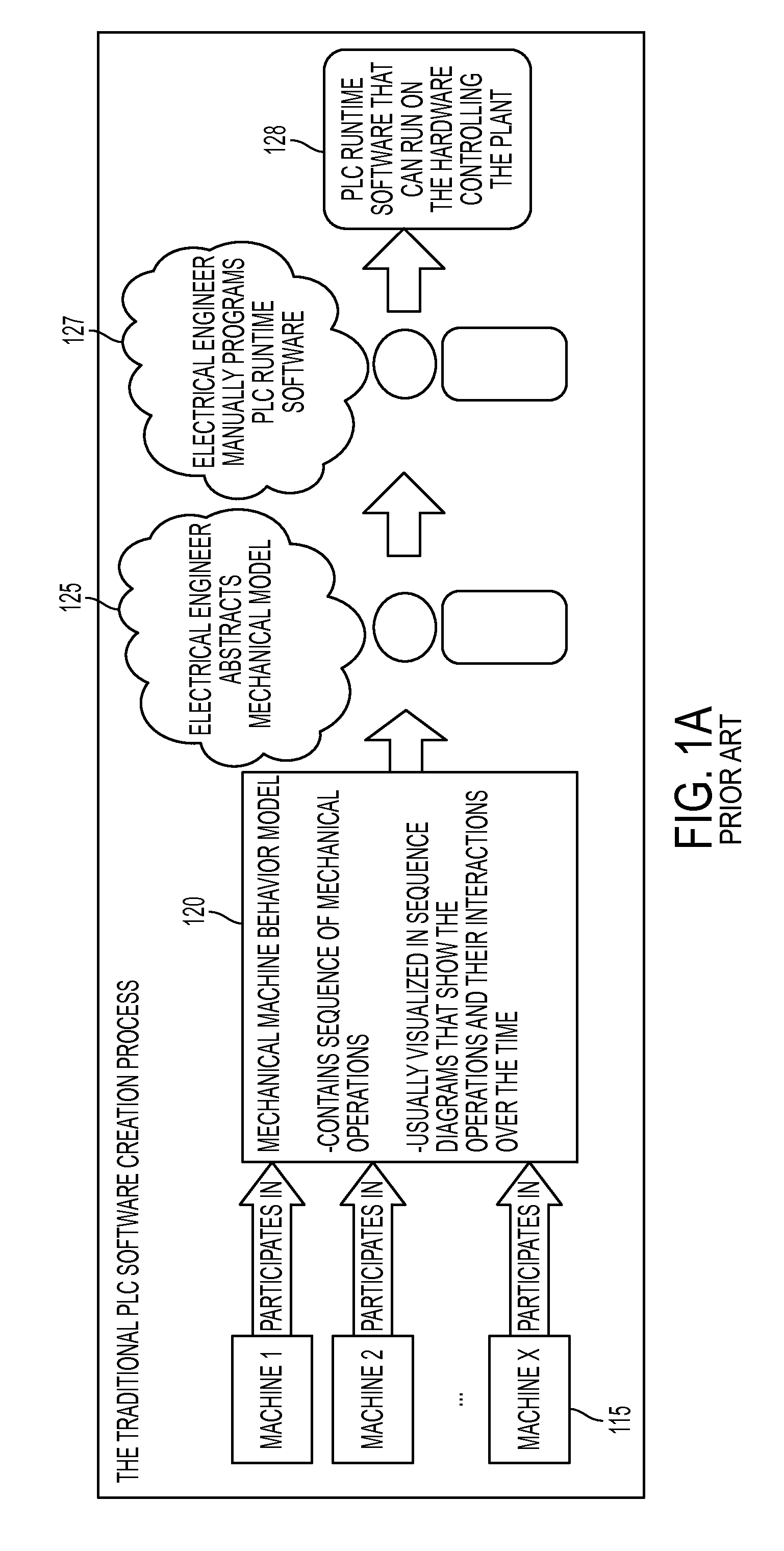
In each case, those traditional systems may be error-prone due to the required manual abstraction and the complexities faced by the engineer, and may be time-consuming for the same reasons.
Method used
View moreImage
Smart ImageViewing Examples

Examples
Embodiment Construction
is to be understood as being in every respect illustrative and exemplary, but not restrictive, and the scope of the invention disclosed herein is not to be determined from the Description of the Invention, but rather from the Claims as interpreted according to the full breadth permitted by the patent laws. It is to be understood that the embodiments shown and described herein are only illustrative of the principles of the present invention and that various modifications may be implemented by those skilled in the art without departing from the scope and spirit of the invention.
Login to View More PUM
 Abstract
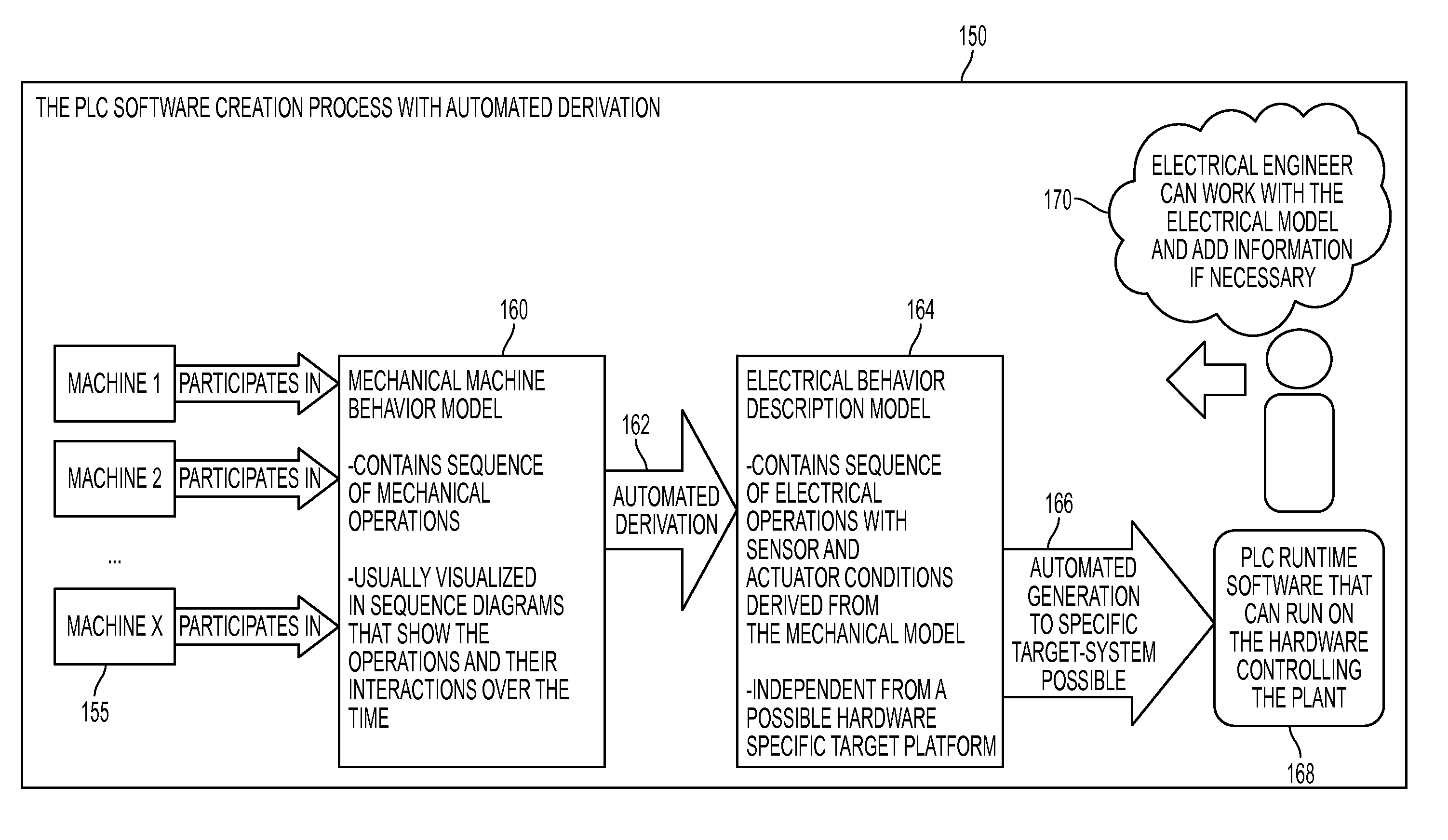
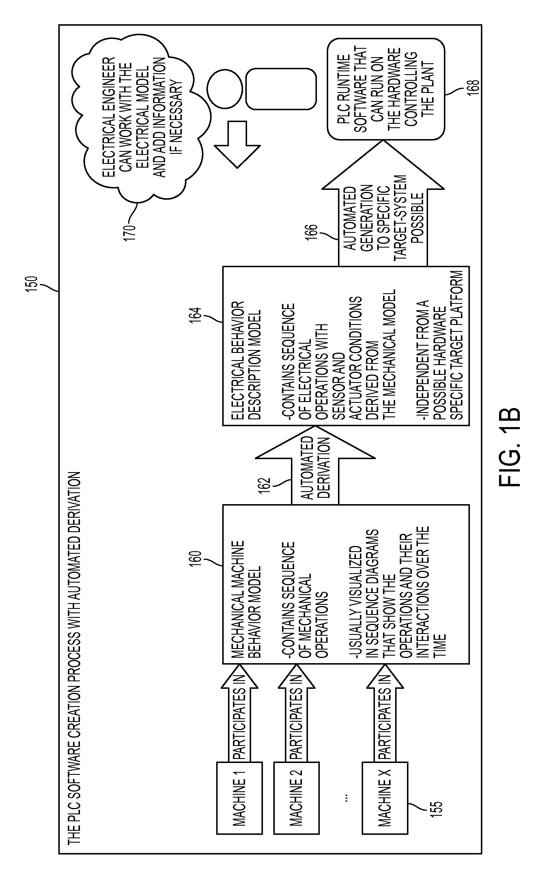
An electrical logic controller behavior model of logic controller behavior is automatically or semi-automatically derived from a model of mechanical machine operation. To create the electrical model, an electrical step is created corresponding to each mechanical step of the mechanical model. For each mechanical transition on the mechanical step, a corresponding electrical transition is created on the corresponding electrical step. For each identified signal associated with an end position of the mechanical step, a condition is created for the associated signal on the corresponding electrical transition. The electrical logic controller behavior model is then used to generate PLC-specific software to control a machine or plant.
Description
CLAIM OF PRIORITY[0001]This application claims priority to, and incorporates by reference herein in its entirety, pending U.S. Provisional Patent Application Ser. No. 61 / 095,995, filed Sep. 11, 2008, and entitled “Automated Derivation of a Logic-Controller-Behavior-Model from a Mechanical-Machine-Operation-Model,” and is related to U.S. patent application Ser. No. ______, filed on the same date as the present application and entitled “Visualization Method for Electrical Machine Operation Models Based on Mechanical Machine Operation Models.”FIELD OF THE DISCLOSURE[0002]The present invention relates generally to the modeling of factory behavior for the purpose of factory automation. More specifically, the invention relates to techniques for deriving an intermediate electrical model of logic controller behavior from a model of mechanical machine operation.BACKGROUND[0003]In the automation field, and more specifically during operational machine planning for a plant, an engineer traditio...
Claims
Login to View More Application Information
Patent Timeline
 Patent Type & AuthorityApplications(United States)
IPC IPC(8): G05B19/05
CPCG05B19/056G05B2219/13147G05B2219/13022
InventorNOETZELMANN, OSWINHELLER, RAINERSCHAUMBURG, DIRK
OwnerSIEMENS AG