
JAVA bytecode translating method

a bytecode and translation method technology, applied in the field of java bytecode translation methods, can solve the problems of degradation, slow execution speed of bytecode analysis, defective java programming language, etc., and achieve the effect of reducing the number of native codes

Inactive Publication Date: 2010-03-11
ADVANCED DIGITAL CHIP
View PDF8 Cites 2 Cited by
  • Summary
  • Abstract
  • Description
  • Claims
  • Application Information

AI Technical Summary

Benefits of technology

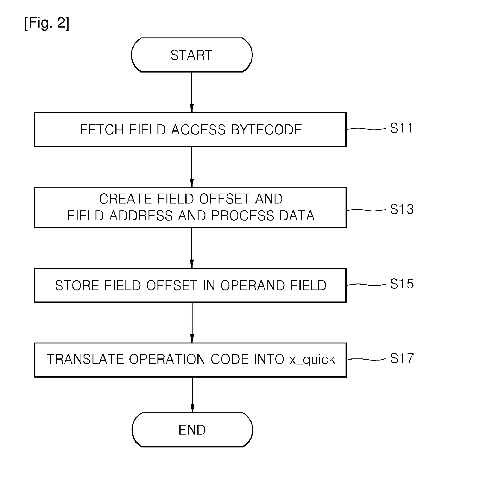
[0040]As described above, the present invention can provide a Java bytecode translating method which includes the steps of: storing a field address created with respect to a bytecode for field access and object field access separately in an operand of a bytecode and a storage portion; then translating an operation code of a corresponding bytecode into a predetermined operation code; gaining access to a field by the field address by data stored in the operand and the storage portion if the bytecode for field access corresponding to the predetermined operation code is fetched, to thus process data and quickly create the field address for static field access and object field access; and reducing the number of native codes that are required at the time of creating the field address.

Problems solved by technology

Java programming language has a defective having a slow execution speed in comparison with a code that is made with language such as C or C++.
However, because analysis of bytecodes is achieved in software, an execution speed of the analysis of bytecodes is slow.
In this case, since several thousands of native codes are usually required only in the case of a process of analyzing the constant pool, degradation occurs when executing Java application programs.
For this reason, the conventional Java bytecode translating method has a problem that degradation still occurs at the time of execution of Java application programs.

Method used


Image

  • JAVA bytecode translating method
  • JAVA bytecode translating method
  • JAVA bytecode translating method

Examples


Embodiment Construction

[0049]Hereinbelow, a Java bytecode translating method according to a preferred embodiment of the present invention will be described with reference to the accompanying drawings. Like reference numerals denote like elements through the following embodiments.

[0050]FIGS. 5 and 6 are flowchart views showing a Java bytecode translating method for static field access according to the present invention, respectively, and FIGS. 7 and 8 are block diagrams for explaining the Java bytecode translating method for static field access according to the present invention, respectively.

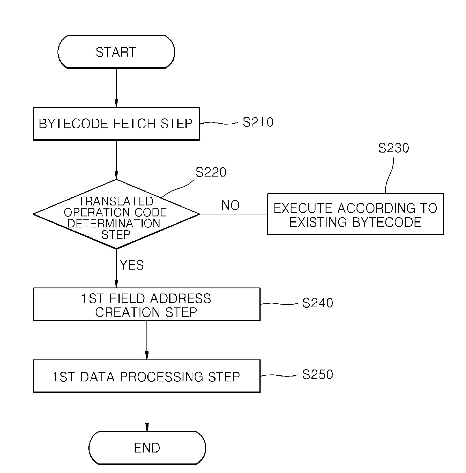
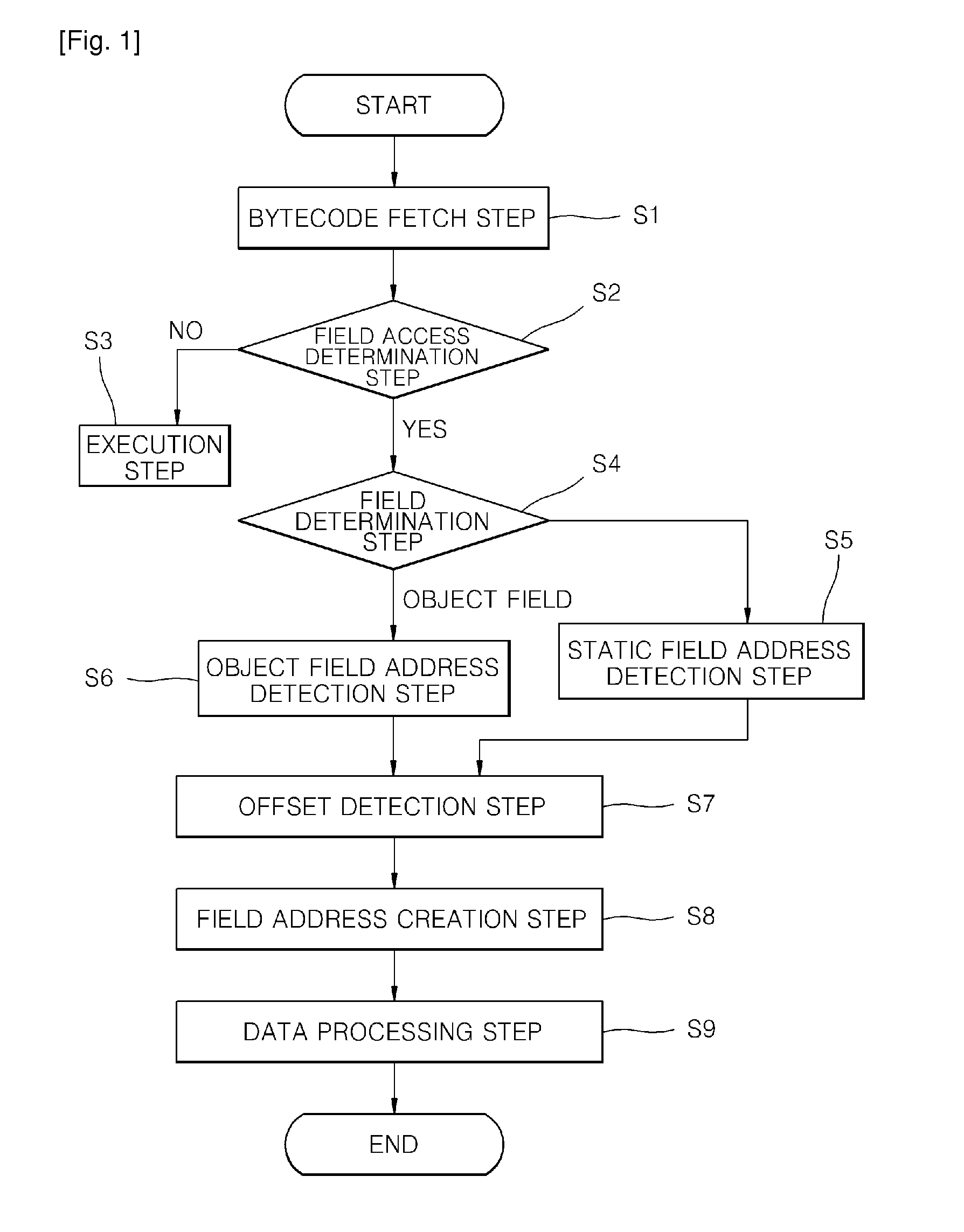
[0051]As illustrated in FIGS. 5 to 8, the Java bytecode translating method according to an exemplary embodiment of the present invention, includes a bytecode fetch step (S110), a static field address detection and data processing step (S140), a static field address storage step (S150), a static operation code translating step (S160), a first field address creation step (S240), and a first data processing step (S250).

[...


PUM


Abstract

Provided is a Java bytecode translating method which includes: a bytecode fetch step (S1 10) that fetches a Java bytecode from a Java class file; a static field address detection and data processing step (S140) which gains access to a field (130) according to a first field address (FA1) and processes data; a static field address storage step (S 150) that stores a first upper field address (FAU1) including upper bits among bits of the first field address (FA1) in a first storage portion (110), and which stores a first lower field address (FAD1) including remainder lower bits excluding the first upper field address (FAU1) among the bits of the first field address (FA1) in an operand field (120b); a static operation code translating step (S 160) that translates an operation code stored in an operation code field (120a) into a new static field accessing operation code (NOPA); a first field address creation step (S240) that creates a second field address (FA2); and a first data processing step (S250) that gains access to the field (130) according to a second field address (F A2) and processes data.

Description

TECHNICAL FIELD[0001]The present invention relates to a Java bytecode translating method, and more particularly to a Java bytecode translating method that can improve performance of a Java virtual machine, in which a field access bytecode is translated without having a progress of an analysis process of a constant pool when performing the field access bytecode among Java bytecodes, to thereby remarkably reduce the number of native codes.BACKGROUND ART[0002]In general, Java language is compiled into intermediate language which is called as Java Virtual Machine Language (JVML) which can be interpreted by a Java Virtual Machine. The compiled result is called as a class file. The class file includes bytecodes.[0003]Because the Java virtual machine bases on an stack operation, all operands are stored in a stack before they are used, and the operation result is also stored in the stack. As a result, the Java virtual machine can run Java application programs which are made up independently...

Claims


Application Information

Patent Timeline
IPC IPC(8): G06F9/44
CPCG06F9/30174G06F9/45508G06F9/44521G06F8/40G06F9/06G06F9/24
Inventor LEE, JONG SUNGOH, HYEONG CHEOLKIM, HYUN GYUKIM, KWAN YOUNG
Owner ADVANCED DIGITAL CHIP
Learn More