Noncontact electric power receiving device, noncontact electric power transmitting device, noncontact electric power feeding system, and electrically powered vehicle

a technology of non-contact electric power and receiving device, which is applied in the direction of electric propulsion mounting, transformer/inductance magnetic core, rail device, etc., and can solve the problem that no specific discussion has been made as to a shielding method

Inactive Publication Date: 2010-03-18
TOYOTA JIDOSHA KK
View PDF11 Cites 348 Cited by
  • Summary
  • Abstract
  • Description
  • Claims
  • Application Information

AI Technical Summary

Benefits of technology

[0022]In the present invention, an electric power transmitting resonator and an electric power receiving resonator, which resonate in an electromagnetic field, are utilized and electric power is transmitted in a noncontact manner from the electric power transmitting resonator to the electric power receiving resonator through the electromagnetic field. Here, an electromagnetism shielding material having an opening at one side thereof to allow the electric power receiving resonator to receive the electric power from the electric power transmitting resonator is provided to surround the electric power receiving resonator. Accordingly, a leakage electromagnetic field generated in the surroundings of the electric power receiving resonator is shielded by the electromagnetism shielding material without preventing the electric power receiving resonator from receiving the electric power from the electric power transmitting resonator. Thus, the present invention allows for appropriate restraint of the leakage electromagnetic field generated when electric power is transmitted in a noncontact manner using the resonance method from the electric power transmitting resonator to the electric power receiving resonator.

Problems solved by technology

However, in the document, no specific discussion has been made as to a shielding method upon electric power transmission.

Method used


Image

  • Noncontact electric power receiving device, noncontact electric power transmitting device, noncontact electric power feeding system, and electrically powered vehicle
  • Noncontact electric power receiving device, noncontact electric power transmitting device, noncontact electric power feeding system, and electrically powered vehicle
  • Noncontact electric power receiving device, noncontact electric power transmitting device, noncontact electric power feeding system, and electrically powered vehicle

Examples


first embodiment

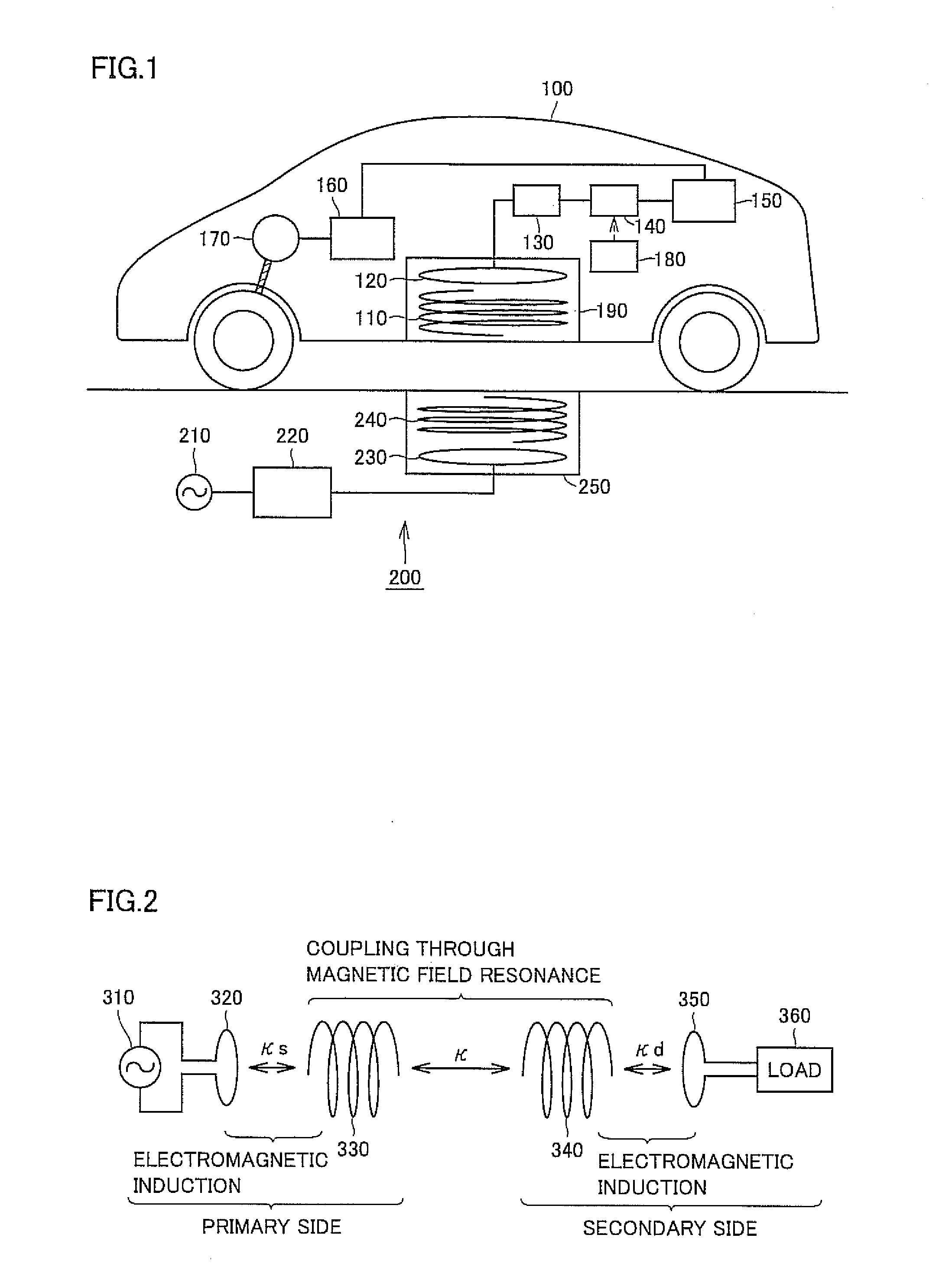
[0031]FIG. 1 shows an entire configuration of an electric power feeding system according to a first embodiment of the present invention. Referring to FIG. 1, the electric power feeding system includes an electrically powered vehicle 100 and an electric power feeding device 200. Electrically powered vehicle 100 includes a secondary self-resonant coil 110, a secondary coil 120, a shielding box 190, a rectifier 130, a DC / DC converter 140, and a power storage device 150. Electrically powered vehicle 100 further includes a power control unit (hereinafter, also referred to as “PCU”) 160, a motor 170, and a vehicular ECU (Electronic Control Unit) 180.

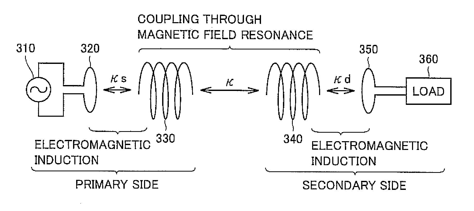
[0032]Secondary self-resonant coil 110 is disposed in, for example, a lower portion of the vehicular body. Secondary self-resonant coil 110 is an LC resonant coil having opposite ends open (unconnected), and resonates with a primary self-resonant coil 240 (described below) of electric power feeding device 200 through an electromagnetic field t...

second embodiment

[0058]In a second embodiment, a configuration for prohibiting reception of electric power in an electrically powered vehicle and a configuration for prohibiting transmission of electric power in an electric power feeding device will be described.

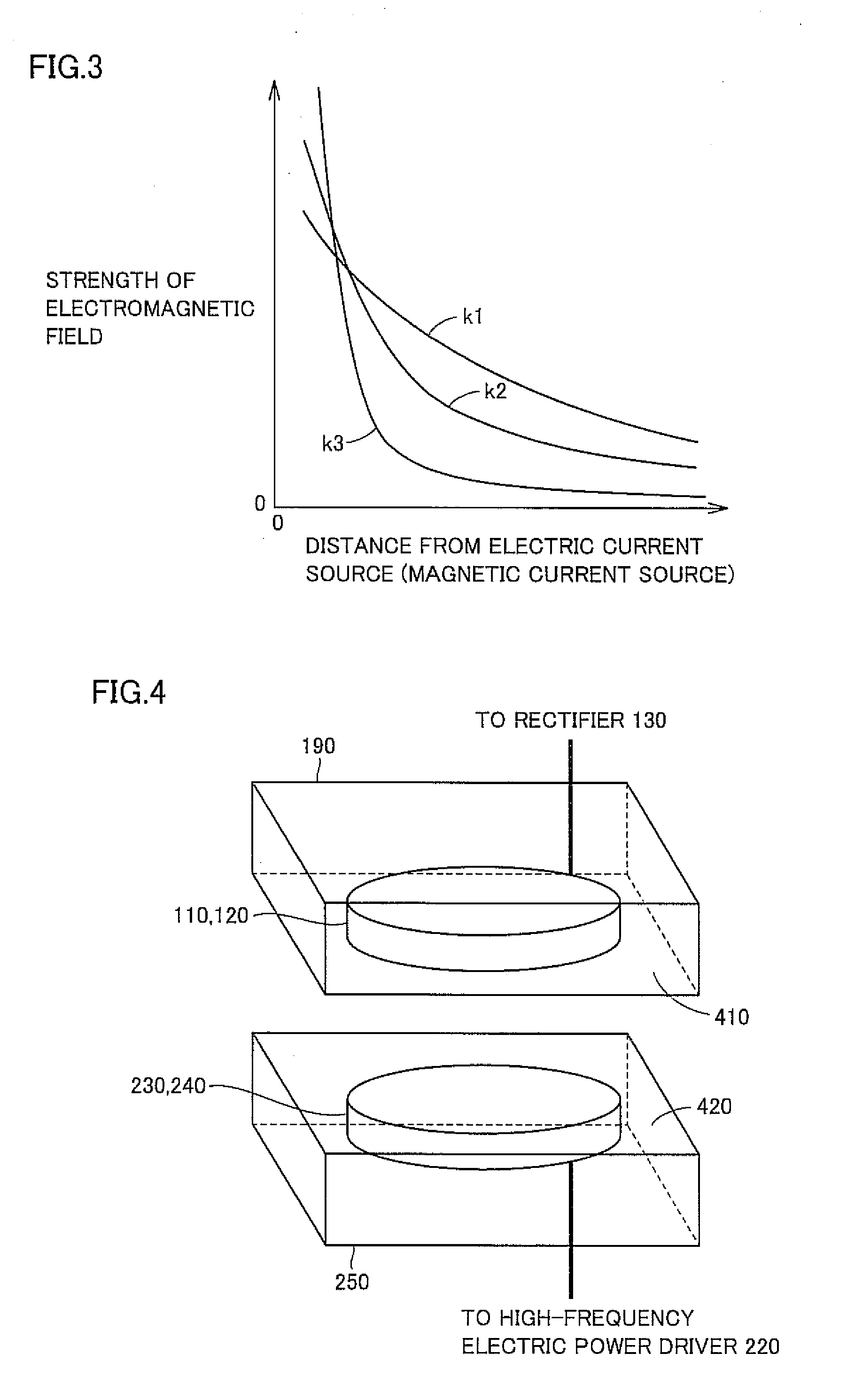
[0059]FIG. 6 is an explanatory diagram of a structure for shielding a resonant electromagnetic field in the second embodiment. Referring to FIG. 6, in the second embodiment, shielding plates 430, 440 are further provided in addition to the configuration of the first embodiment shown in FIG. 4.

[0060]Shielding plate 430 is configured to be slidable and can cover surface 410 of shielding box 190. When the electrically powered vehicle receives electric power from the electric power feeding device, shielding plate 430 is moved to expose surface 410. Meanwhile, when no electric power is received or reception of electric power needs to be stopped urgently due to some abnormality, shielding plate 430 is moved to be interposed between the electric po...


PUM

PropertyMeasurementUnit
frequencyaaaaaaaaaa
electromagnetic fieldaaaaaaaaaa
electric poweraaaaaaaaaa

Abstract

A first shielding box is disposed so that its first surface can be opposite to an electric power feeding unit. The first surface has an opening and remaining five surfaces thereof reflect, during reception of electric power from the electric power feeding unit, a resonant electromagnetic field (near field) generated in the surroundings of the electric power receiving unit. The electric power receiving unit is provided in the first shielding box to receive the electric power from the electric power feeding unit via the opening (first surface) of the first shielding box. A second shielding box has a similar configuration, i.e., has a second surface with an opening and remaining five surfaces thereof reflect the resonant electromagnetic field (near field) generated in the surroundings of the electric power feeding unit.

Description

[0001]This nonprovisional application is based on Japanese Patent Application No. 2008-239622 filed on Sep. 18, 2008 with the Japan Patent Office, the entire contents of which are hereby incorporated by reference.BACKGROUND OF THE INVENTION[0002]1. Field of the Invention[0003]The present invention relates to a noncontact electric power receiving device, a noncontact electric power transmitting device, a noncontact electric power feeding system, and an electrically powered vehicle, in particular, a shielding technique in an electric power feeding system that employs a resonance method to supply electric power from a power source external to a vehicle to the vehicle in a noncontact manner.[0004]2. Description of the Background Art[0005]As environmental friendly vehicles, electrically powered vehicles such as an electric vehicle and a hybrid vehicle are drawing attention greatly. These vehicles have a motor for generating driving force for traveling, and a rechargeable power storage de...

Claims


Application Information

Patent Timeline
Patent Type & Authority Applications(United States)
IPC IPC(8): B60K1/00H01F38/14B60M7/00H02J7/00
CPCB60L11/182H01F27/26H01F38/14B60L2270/147Y02T10/7005Y02T90/122Y02T90/14H04B5/0093B60L53/12Y02T10/70Y02T10/7072Y02T90/12
Inventor ICHIKAWA, SHINJI
Owner TOYOTA JIDOSHA KK
Why Eureka
Try Eureka