Pipe-joining method and apparatus for producing underwater pipelines, and underwater-pipeline-laying vessel comprising such an apparatus

a pipe-joining method and pipeline technology, applied in the direction of machines/engines, auxillary welding devices, auxillary cutting devices, etc., can solve the problems of excessive time-consuming and inconvenient application of the third coat, and achieve the effect of eliminating the drawbacks of the known ar

Active Publication Date: 2010-03-18
SAIPEM SPA
View PDF15 Cites 20 Cited by
  • Summary
  • Abstract
  • Description
  • Claims
  • Application Information

AI Technical Summary

Benefits of technology

[0017]Extruding the protective sheet close to the cutback means it can be applied to the cutback while still in the plastic state and at such a temperature as to achieve improved, relatively fast adhesion to the underlying coats and to the first coating. And the even temperature along the whole of the protective sheet means the whole cutback can be coated with a single protective sheet extruded to a suitable thickness.

Problems solved by technology

All the above methods of applying the third coat are extremely time-consuming.
In other words, since, in most cases, the mass of polymer material to be applied to form the third coat is relatively considerable, and the third coat must be plastic enough, when applied, to achieve effective chemical / mechanical adhesion to the second coat, known methods of applying the third coat do not allow a satisfactory reduction in coating time.

Method used


Image

  • Pipe-joining method and apparatus for producing underwater pipelines, and underwater-pipeline-laying vessel comprising such an apparatus
  • Pipe-joining method and apparatus for producing underwater pipelines, and underwater-pipeline-laying vessel comprising such an apparatus
  • Pipe-joining method and apparatus for producing underwater pipelines, and underwater-pipeline-laying vessel comprising such an apparatus

Examples


Embodiment Construction

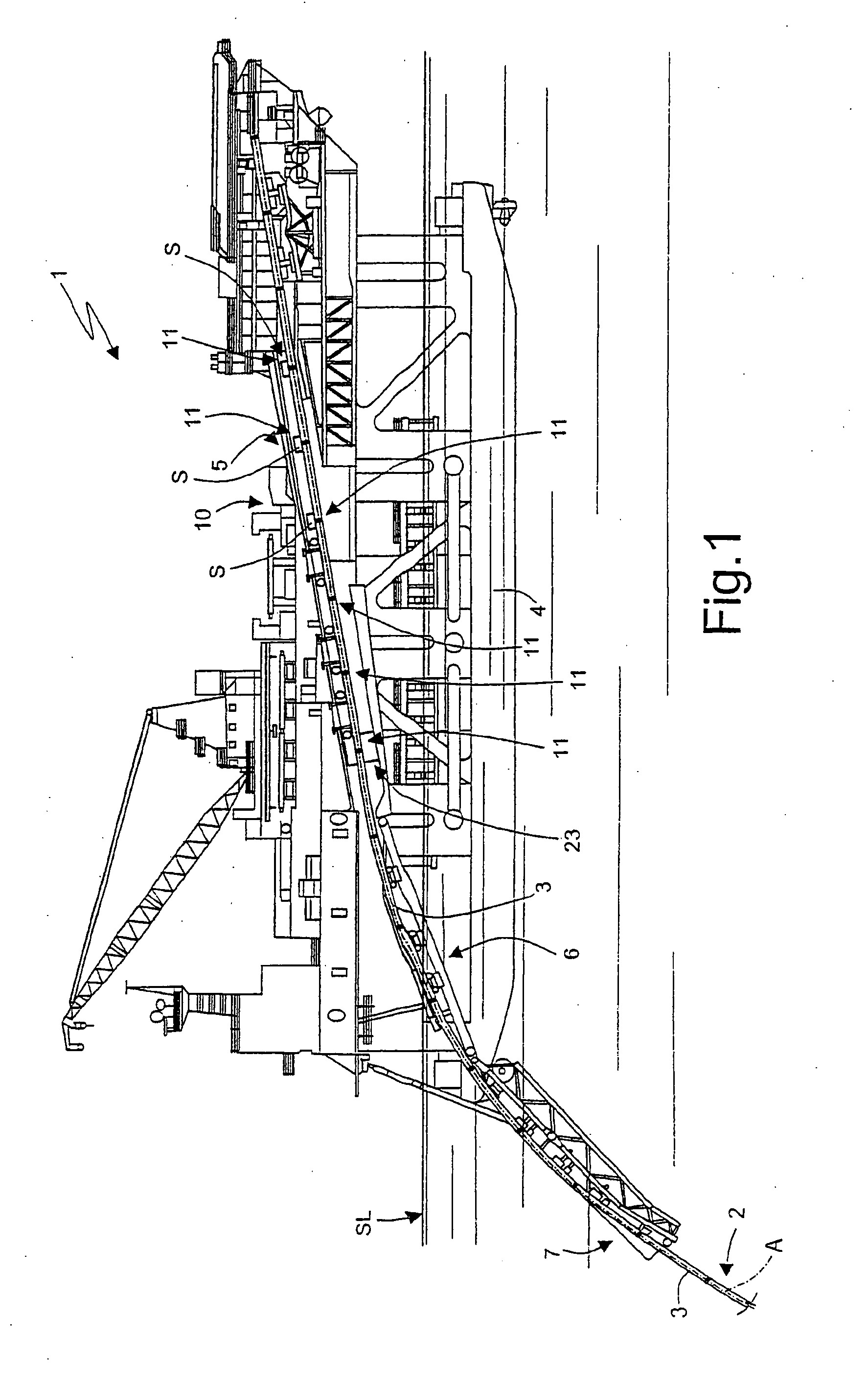
[0029]Number 1 in FIG. 1 indicates a pipeline-laying vessel in the process of producing and laying in the sea (SL indicates sea level) an underwater pipeline 2 comprising pipes 3 joined to one another. Vessel 1 comprises hulls 4; an above-water tunnel 5; a partly above-water, inside ramp 6; an underwater outside ramp 7; and a work line 10 extending along tunnel 5 and the above-water portion of inside ramp 6.

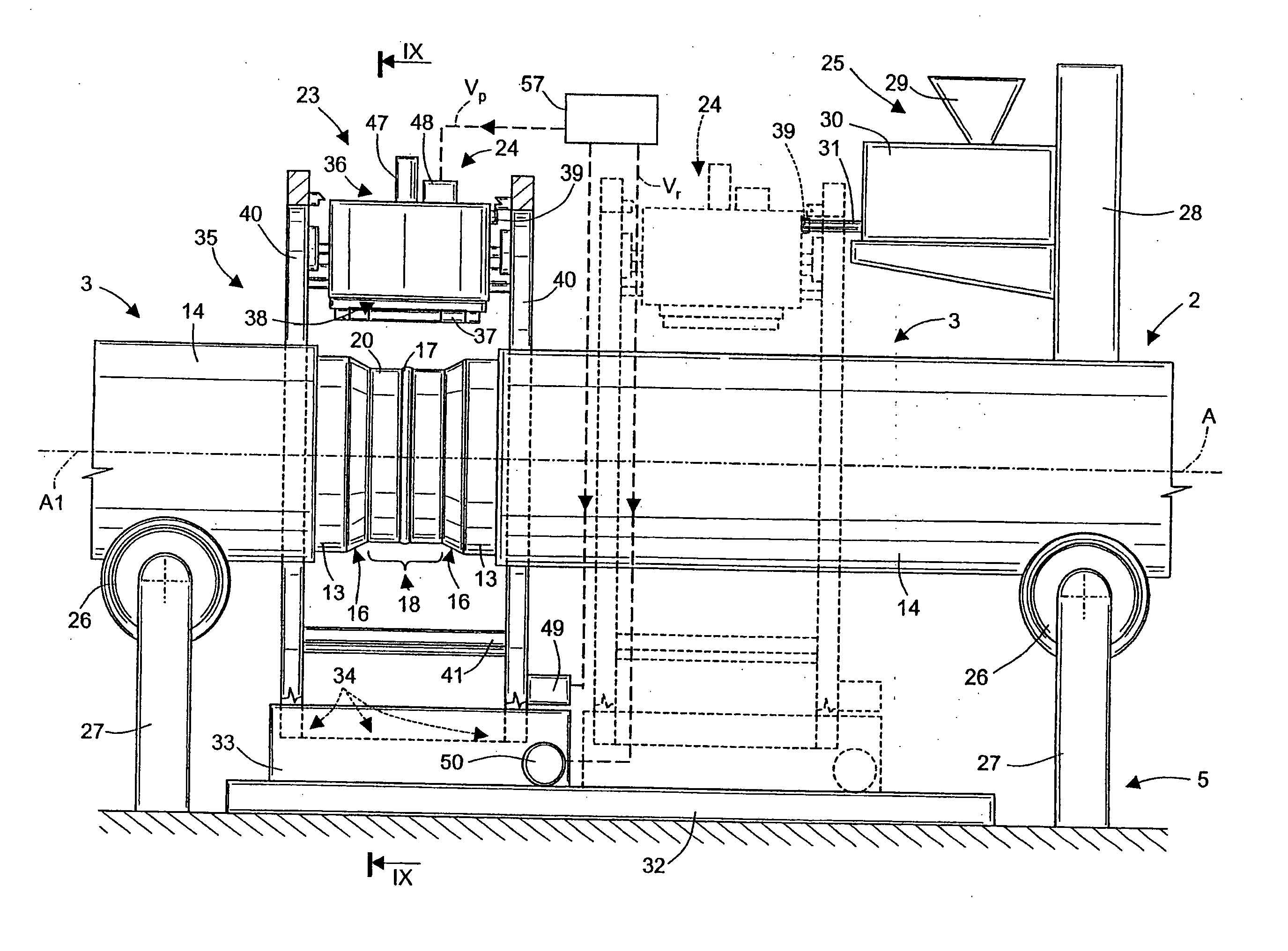
[0030]The partly formed underwater pipeline 2 and pipes 3 ready for joining to it extend along an axis A of work line 10, which comprises a number of joining stations 11 equally spaced along axis A, and each for performing a given operation, such as welding, non-destructive testing, or bridging a coating.

[0031]The distance between adjacent joining stations 11 equals the standard length, about 12 metres, of each pipe 3, or a multiple of the standard length, when joining, along line 10, multiple-standard-length pipes 3 joined beforehand at on-land installations or off-line on the v...


PUM

PropertyMeasurementUnit
diametersaaaaaaaaaa
diametersaaaaaaaaaa
diameteraaaaaaaaaa

Abstract

A method of joining pipes (3) to produce underwater pipelines (2), wherein the facing free ends (15) of two adjacent pipes (3), aligned along an axis (A), are welded to define a cutback (18); a protective sheet (22) of plastic material is extruded close to the cutback (18); and the protective sheet (22) is wound about the cutback (18).

Description

TECHNICAL FIELD[0001]The present invention relates to a pipe-joining method for producing an underwater pipeline.[0002]The method according to the present invention comprises welding the facing free ends of two adjacent pipes, aligned along an axis, to form an annular joint portion known as cutback; and applying a protective sheet about the cutback.BACKGROUND ART[0003]Underwater pipelines comprise a number of pipes joined to total lengths of hundreds of kilometers. The pipes are of normally 12-metre standard length, and relatively large diameters ranging between 0.2 and 1.5 metres, and each comprise a steel cylinder; a first coating of polymer material to protect the steel pipe; and possibly a second coating of Gunite or cement to weigh down the pipe. In some applications, the pipes and underwater pipelines do not need and therefore have no second coating.[0004]To weld the steel cylinders to one another, the opposite free ends of each pipe have no first or second coating. The pipes ...

Claims


Application Information

Patent Timeline
Patent Type & Authority Applications(United States)
IPC IPC(8): B23K31/02B23K28/00B23K37/00B29C48/08B29C48/12B29C48/30B29C48/92
CPCB23K37/0533B29C2947/92904B29C47/0021B29C47/021F16L1/26F16L13/0272F16L58/181F16L13/00B29C47/0866B29C47/028B29C47/0806B29C47/126B29C47/92B29C2947/9258B29C2947/926B23K2201/10B29C65/483B29C66/0242B29C66/112B29C66/1122B29C66/12821B29C66/1286B29C66/5326B29C66/652B29C66/71B29C66/72321B29C66/7392B29C66/742B29C66/74283B29C66/8362B29C65/028B29C65/522B23K2101/10B29C48/92B29C48/151B29C48/157B29C48/266B29C48/303B29C48/2528B29C48/08B29C2948/926B29C2948/9258B29C2948/92904B29C48/12B29K2023/06B29K2023/12
Inventor CITTADINI BELLINI, SERAFINO
Owner SAIPEM SPA
Why Eureka
Try Eureka