Method of compression-molding light-emitting elements

a technology of light-emitting elements and compression molding, which is applied in the direction of optical articles, other domestic articles, solid-state devices, etc., can solve the problems of preventing efficient improvement in and achieve the effect of efficiently improving the manufacturing efficiency of products and preventing the formation of resin burrs

Inactive Publication Date: 2010-03-18
TOWA
View PDF0 Cites 41 Cited by
  • Summary
  • Abstract
  • Description
  • Claims
  • Application Information

AI Technical Summary

Benefits of technology

[0023]The present invention has the beneficial effect of providing a method of compression-molding light-emitting elements which can efficiently prevent the formation of a resin burr on a frame on which light-emitting elements (e.g. L...

Problems solved by technology

The presence of these processes prevents efficient improveme...

Method used


Image

  • Method of compression-molding light-emitting elements
  • Method of compression-molding light-emitting elements
  • Method of compression-molding light-emitting elements

Examples


first embodiment

[0077]The first embodiment of the present invention is hereinafter detailed on the basis of the drawings illustrating the embodiment.

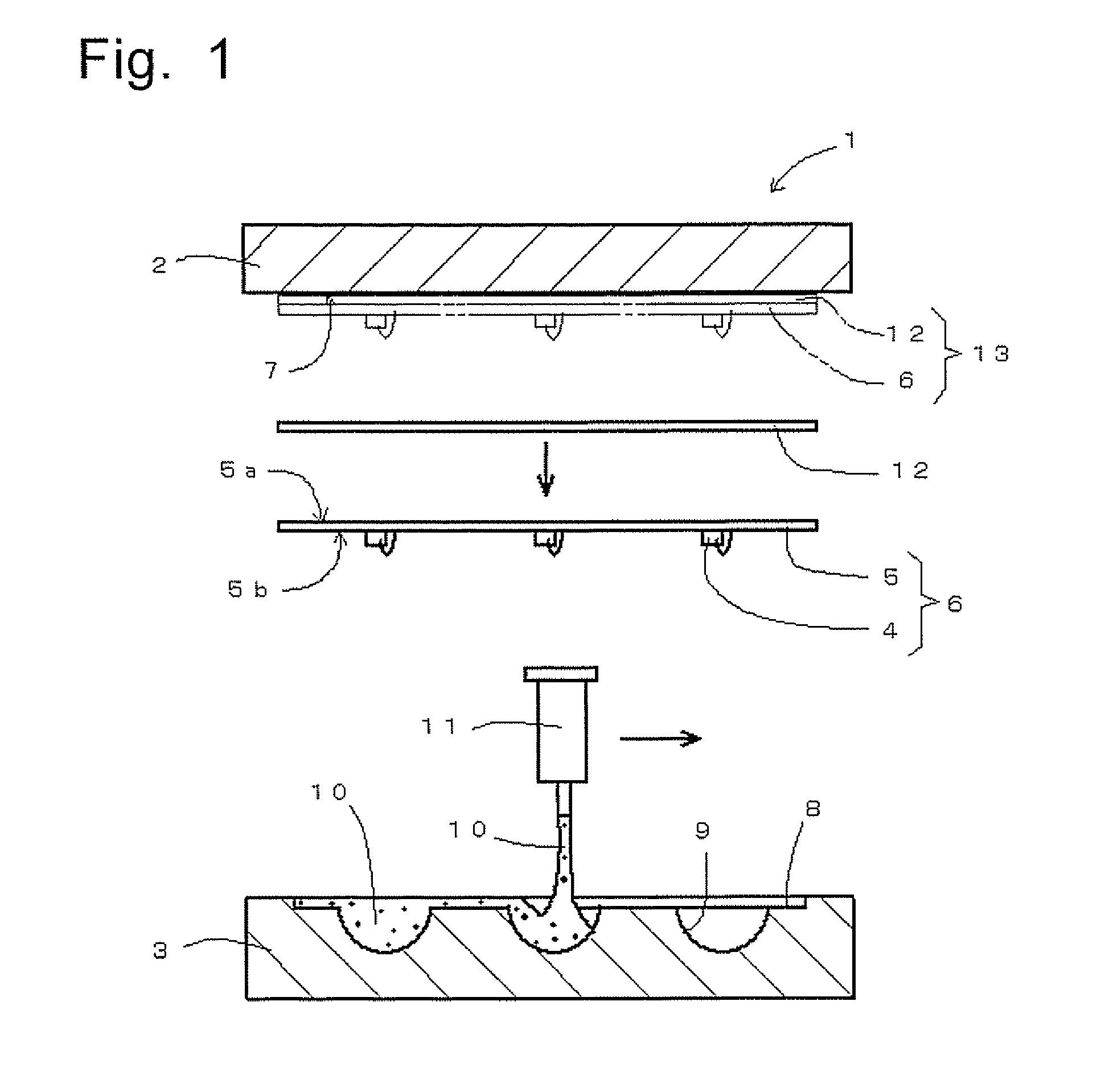
[0078]FIGS. 1, 2 and 3 show a molding die for compression-molding light-emitting elements according to the first embodiment.

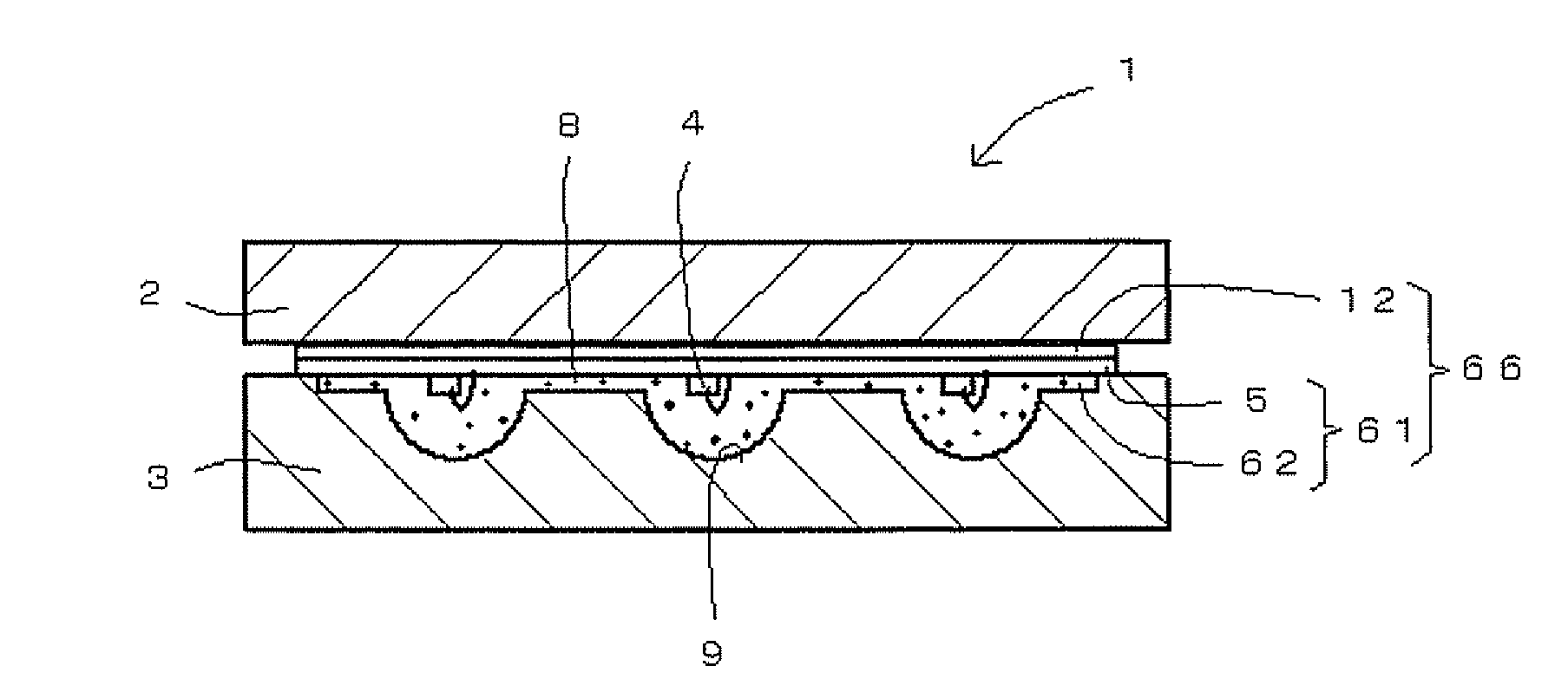
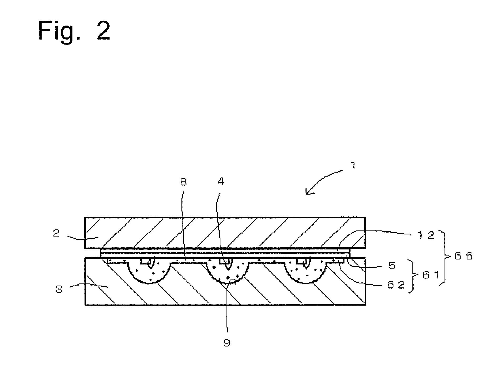
[0079]The molded frame (light emitter) shown in FIG. 6(1) has been compression-molded with the molding die shown in FIGS. 1, 2 and 3.

(Details of Molded Frame)

[0080]The molded frame 61 shown in FIG. 6(1) consists of a frame 5 and a collective resin-molded light-emitting body 62 with transparency (optical permeability). The collective resin-molded light-emitting body 62 consists of a base part 63 formed on the frame 5 and a required number of light-emitting parts (lens parts) 64.

[0081]Each of the light-emitting parts 64 is created by compression-molding (resin encapsulation) an LED chip 4 mounted on the frame 5. The molded frame 61 (with a required number of LED chips 4) can function as a surface emission light source.

[0082]It is al...

second embodiment

[0116]The second embodiment is hereinafter described using FIGS. 4 and 5.

[0117]The molding die for compression-molding light-emitting elements shown in FIGS. 4 and 5 is a three-piece type, including the upper, central and lower dies. However, its basic configuration is the same as that of the two-piece type molding die described in the first embodiment.

[0118]Using the molding die shown in FIGS. 4 and 5 in the compression-molding will result in a molded frame shown in FIG. 6(2).

[0119]As in the first embodiment, the method in the second embodiment uses an ante-molding frame with a required number of LED chips mounted thereon and a tape for resin burr prevention.

(Details of Molded Frame)

[0120]The molded frame 71 shown in FIG. 6(2) consists of a frame 5 and a number of individual resin-molded light-emitting bodies (light-emitting parts) 72 with transparency (optical permeability).

[0121]Each of the light-emitting parts 72 is created by compression-molding (resin-encapsulating) an LED chi...

third embodiment

[0150]A vertical sectional view of a compression-molding molding die as the third embodiment is shown in FIG. 8. This mold uses a release film 41 in place of the tape. Such a film has been generally used for mold-releasing purposes.

[0151]In the molding process, the upper and lower dies are opened, and then the release film 41 is inserted between the frame 5 and the fixed upper die 2. There are several methods for inserting the release film 41: placing the film on the upper surface of the frame 5, fixing the film to the lower surface of the fixed upper die 2, or sandwiching the film between the frame 5 and the upper die 2. For fixing the film to the lower surface of the fixed upper die 2, one method is to create vacuum holes in the lower surface of the upper die and draw air through these holes to hold the release film 41 by suction; another method is to bond the film with a weak adhesive. For holding the film between the frame 5 and the fixed upper die 2, one method is to make the r...


PUM

PropertyMeasurementUnit
Pressureaaaaaaaaaa
Transparencyaaaaaaaaaa
Vacuumaaaaaaaaaa

Abstract

A method of compression-molding light emitting elements is provided, which can efficiently prevent the formation of a resin burr on a frame on which LED chips (light-emitting elements) are mounted. A tape for resin burr prevention is adhered to a surface of the frame, i.e. the surface on which no light-emitting element is mounted, to form a tape-applied frame. The tape-applied frame is supplied and set onto a setting section of an upper die, with the LED chips directed downwards. A required amount of transparent liquid resin material is dripped by a dispenser into a large cavity including small cavities. Then, both the upper and lower dies are clamped with a required clamping pressure, whereby the LED chips are individually immersed in the resin contained in the small cavities inside the large cavity and compression-molded to form a molded frame (light emitters).

Description

TECHNICAL FIELD[0001]The present invention relates to a method of compression-molding light-emitting elements, in which light-emitting diode (LED) chips or similar light-emitting elements mounted on a frame are compression-molded with a transparent resin material to form a light emitter (product).BACKGROUND ART[0002]Light emitters using LED chips or similar light-emitting elements have been manufactured and used for years. For example, a type of generally used light emitter is manufactured as follows.[0003]As shown in FIG. 7(1), a light-emitting device body 82 having a cavity 83 with a trapezoid sectional shape is mounted on a frame 81. After an LED chip 84 is set in the cavity 83, a transparent liquid resin material 86 is dripped from a dispenser 85 into the cavity 83 to form a light-emitting device 87 (light-emitting part). Subsequently, a pre-molded lens member 89 (which is a convex lens in the illustrated example) is bonded onto the emission surface 88 of the light-emitting devi...

Claims


Application Information

Patent Timeline
IPC IPC(8): B29C43/18H01L33/54H01L33/56
CPCB29C33/0022H01L2933/005B29C43/18B29C2043/3438H01L24/97H01L2224/48091H01L2224/48227H01L2224/97H01L2924/01004H01L2924/01033H01L2924/01082B29C43/021H01L2924/12041H01L2924/01006H01L2924/00014H01L2224/85B29D11/00298B29D11/00807H01L2924/181H01L2924/00B29C43/34B29C43/38B29L2011/00
Inventor KAWAKUBO, KAZUKI
Owner TOWA
Why Eureka
Try Eureka