Cup seal and master cylinder using the same

a technology of master cylinder and seal, applied in mechanical equipment, braking systems, transportation and packaging, etc., can solve the problems of insufficient pumping performance of the outer lip portion d, and achieve the effect of improving sealing performance, high hydraulic pressure, and smooth flow of hydraulic fluid

Inactive Publication Date: 2010-03-18
BOSCH CORP
View PDF7 Cites 16 Cited by
  • Summary
  • Abstract
  • Description
  • Claims
  • Application Information

AI Technical Summary

Benefits of technology

[0019]According to the cup seal of the invention constituted as described above, the first seal portion of the outer lip portion comes into close contact with the bottom wall of the recessed portion to attain the sealing relative to the bottom wall on the outer periphery of the outer lip portion for the flow of the hydraulic fluid from the outer lip portion toward the base portion, and the second seal portion of the base portion comes into close contact with the second side wall of the recessed portion on the side opposite to the first side wall of the recessed portion to which the tip portion of the outer lip portion faces to attain the sealing relative to the second side wall. Therefore, a double seal portion is constituted being arranged in series for the flow of the hydraulic fluid from the outer lip portion to the base portion. Therefore, the cup seal features improved sealing performance and maintains the high hydraulic pressure of a high degree in the flow of the hydraulic fluid from the outer lip portion to the base portion on the upstream of the first seal portion of the outer lip portion.
[0020]Further, the first seal portion of the outer lip portion separates away from the bottom wall of the recessed portion to form the gap relative to the bottom wall on the outer periphery of the outer lip portion for the flow of the hydraulic fluid from the base portion to the outer lip portion, and the second seal portion of the base portion separates away from the second side wall to form the gap relative to the second side wall. Therefore, the cup seal works to smoothly flow the hydraulic fluid from the base portion to the outer lip portion on the upstream of the second seal of the base portion.
[0021]Further, a predetermined number of intermediate lip portions are circularly and intermittently arranged in the circumferential direction maintaining a predetermined gap in a manner that no intermediate lip portion is present in the portions among the neighboring intermediate lip portions, enabling the outer lip portion to easily deflect inward in the radial direction. On the outer peripheral side of the outer lip portion, therefore, the hydraulic fluid is allowed to flow more...

Problems solved by technology

If the thickness of the outer lip portion d is simply increased, however, there arouses a prob...

Method used


Image

  • Cup seal and master cylinder using the same
  • Cup seal and master cylinder using the same
  • Cup seal and master cylinder using the same

Examples


Embodiment Construction

[0031]Described below with reference to the drawings is the best mode for carrying out the invention.

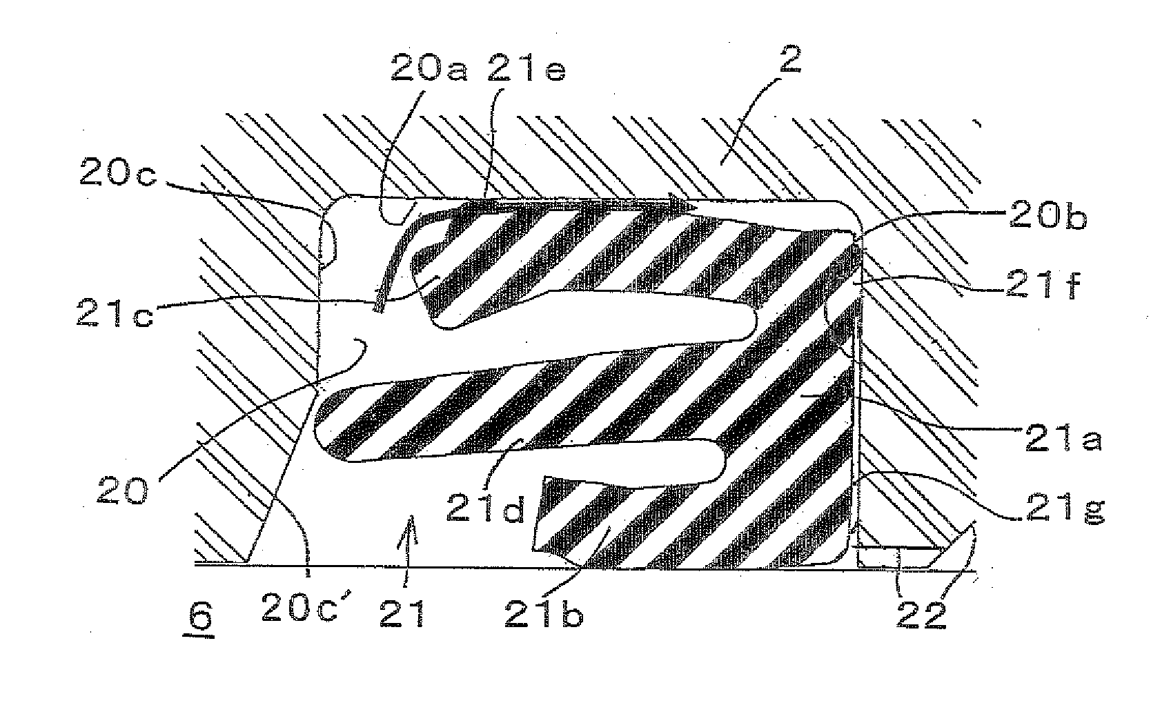
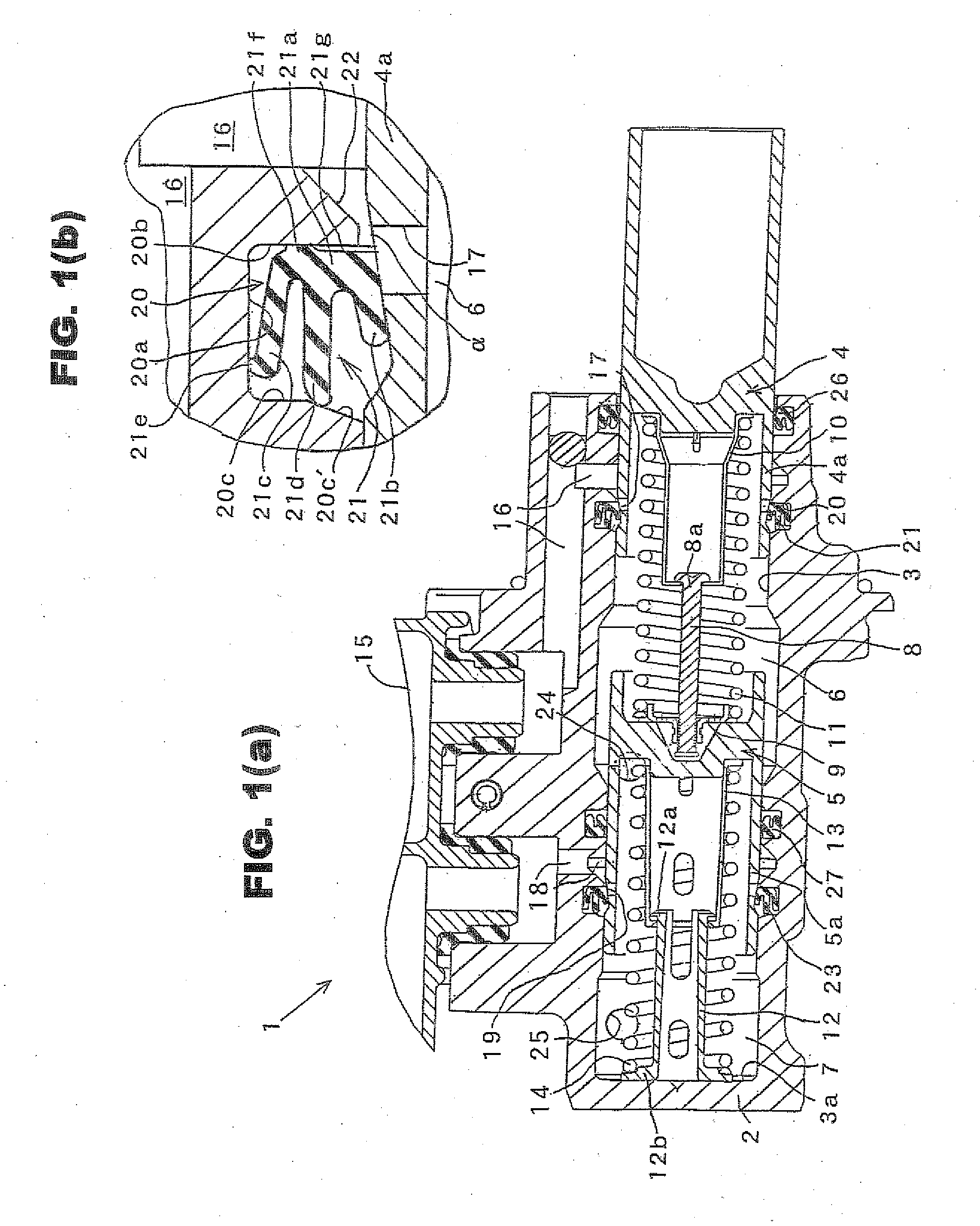
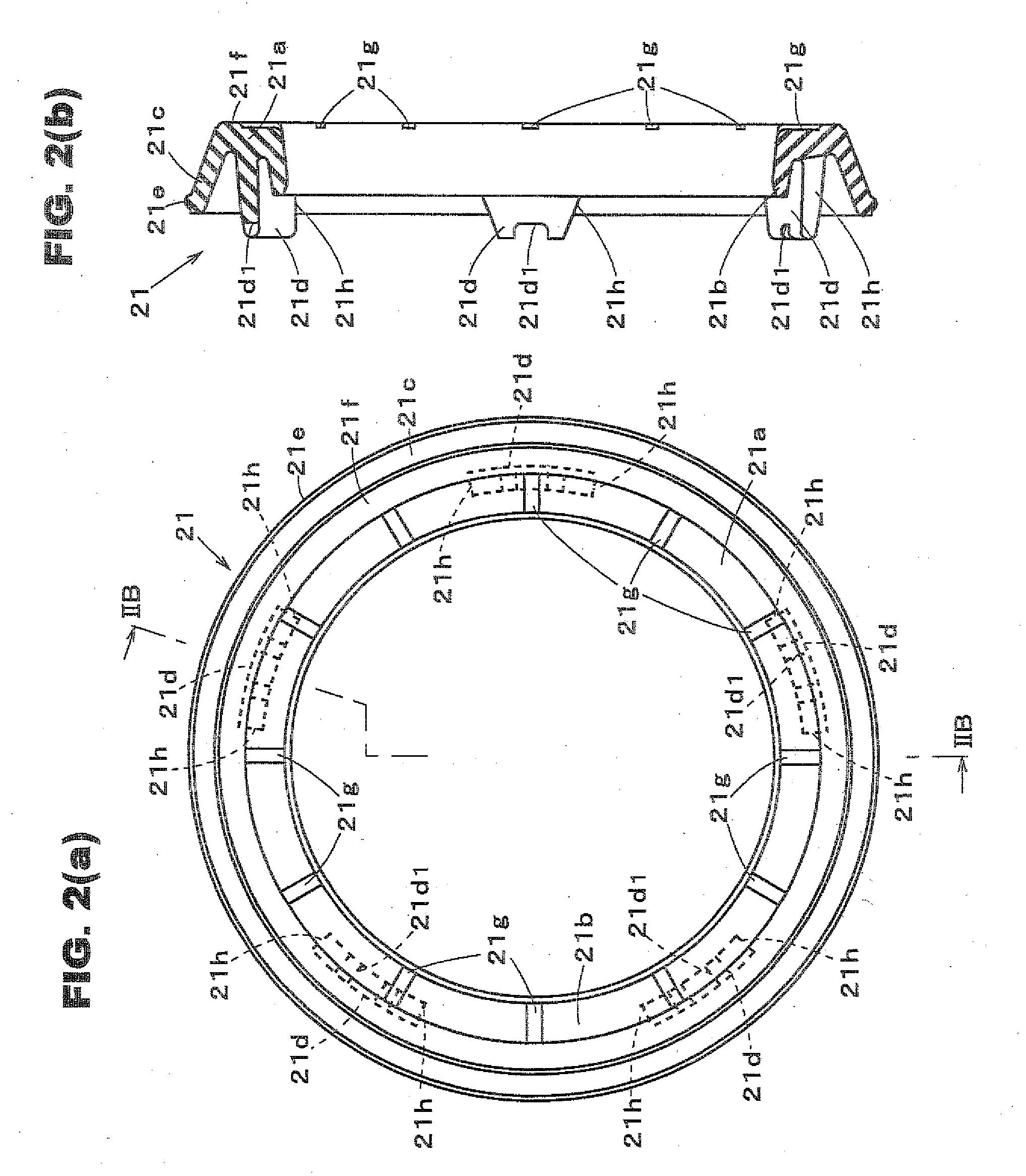
[0032]FIG. 1(a) is a vertical sectional view illustrating an embodiment of a master cylinder equipped with a cup seal according to the invention, FIG. 1(b) is a view illustrating, on an enlarged scale, a portion of a first cup seal portion in FIG. 1(a), and FIGS. 2(a) and (b) are views illustrating the cup seal used for the master cylinder. In the following description, the front and back of the master cylinder are the left and right in the drawings, respectively.

[0033]Referring to FIG. 1(a), a plunger type master cylinder 1 is used as the master cylinder of a brake system and includes a cylinder body 2. A cylinder hole 3 is formed in the cylinder body 2.

[0034]A primary piston 4 and a secondary piston 5 are inserted in the cylinder hole 3 so as to slide therein. The primary piston 4 is moved leftward by a brake pedal or by a brake booster that multiplies the depressing force of the b...


PUM


Abstract

In a cup seal, the hydraulic pressure in a first hydraulic chamber (6) causes a first seal portion (21e) of an outer lip portion (21c) to closely contact to a bottom wall (20a) of a recessed portion (20) and causes a second seal portion (21f) of a base portion (21a) to closely contact to a rear surface (20b) of the recessed portion (20). A double seal due to the first and second seal portions (21e) and (21f) reliably prevents the leakage of a brake fluid from the first hydraulic chamber (6). If the pressure becomes negative in the first hydraulic chamber (6), the tip portion of the outer lip portion (21c) deflects inward and the outer peripheral end of the base portion (21a) deflects forward. Therefore, the brake fluid in the reservoir flows into the first hydraulic chamber (6) through the gaps among the second and first seal portions (21f), (21e) and the wall surface of the recessed portion (20) to maintain fluid-feeding performance.

Description

BACKGROUND ART[0001]This invention relates to a technical field of a cup seal used for a cylinder device including a cylinder such as a master cylinder of a brake or a clutch and a slide member arranged in the cylinder so as to undergo a relative motion in the axial direction thereof, and a master cylinder of the plunger type equipped with the cup seal in a vehicle such as automobile.[0002]The hydraulic brake systems and the hydraulic clutch systems of automobiles are conventionally employing a master cylinder that generates a hydraulic pressure depending upon the force of depressing the brake pedal or the clutch pedal to operate the brake or the clutch. As the master cylinder, there has been known a plunger type master cylinder as disclosed in JP-A-2003-261020.[0003]The plunger type master cylinder comprises a cylinder body having a cylinder hole, a piston inserted in the cylinder hole and slides therein to divide the hydraulic chamber, a connecting passage provided in the cylinder...

Claims


Application Information

Patent Timeline
IPC IPC(8): F16J15/32B60T11/236B60T11/16F16J15/18F16J15/3232F16J15/3236
CPCB60T11/236B60T11/232F16J15/32B60T11/16
Inventor AOKI, TOMOHIROSHIWA, MASAKI
Owner BOSCH CORP
Why Eureka
Try Eureka