Controlling propeller rotor overspeed

a technology of propeller rotor and control rotor, which is applied in the direction of mechanical power/torque control, ratio control, position/direction control, etc., can solve the problems of engine overspeeding, self-destruction of the rotor stage, and rotor may be commanded to pivot too far, so as to achieve a more flexible control method and quick action response

Active Publication Date: 2010-03-18
ROLLS ROYCE PLC
View PDF57 Cites 0 Cited by
  • Summary
  • Abstract
  • Description
  • Claims
  • Application Information

AI Technical Summary

Benefits of technology

[0011]There may be more than one electrical load, each load being switchable into a high load state in response an overspeed signal. This provides flexibility to add lots or some load as required to control the overspeed condition without overloading the electrical generation means.
[0013]The engine may further have a detector to detect a rotor overspeed condition and produce the overspeed signal. The detector may also detect an impending overspeed condition and produce the overspeed signal. This has the benefit of enabling the load or loads to be switched into a high load state to reverse a tendency towards overspeed as well as an actual overspeed condition.
[0017]This is beneficial because it utilises the excess speed of the rotor stage to draw additional power for the load to slow the propeller stage and thereby control the overspeed.
[0018]The step of detecting the overspeed signal may comprise detecting when the at least one stage is within a predetermined overspeed range. This enables the controlling method to begin before the engine has reached overspeed and thereby provide a more timely and quicker acting response.
[0019]The engine may have more than one load and the switching step comprise switching at least one load into a high load state, or may comprise switching at least one load into a high load state and at least one other load into a normal load state. This provides more flexibility in the method of controlling rotor overspeed.

Problems solved by technology

However, one problem with providing propeller rotor stages with variable pitch blades is that the pitch may be commanded to pivot too far, or may fail with the same effect.
In this situation the blades are driven by the airflow and transmit torque to the core engine, rather than being driven by the core engine, which causes the engine to start overspeeding.
If not rapidly controlled, overspeed can cause excessive forces and result in self-destruction of the rotor stage leading to expulsion of high-energy debris.
Too fine a blade angle also results in excessive drag, which has a detrimental effect on the performance of the engine and aircraft and may, at extreme angles, cause hazardous or catastrophic loss of control of the aircraft.
Conversely, if the pitch of the blades is commanded to or fails at too coarse an angle the blades begin to feather.
One problem with this approach is that the engine speed is usually minimised prior to transitioning to reverse thrust so that there is a greater speed margin available for the speed surge through fine pitch.
This means that if the aircraft needs to go-around, and therefore demands a rapid increase in power from the engine, there is a much larger speed increase required to meet the demand.
A further problem is that if there is a minor problem during transition, for example slower than normal transition, an overspeed may occur anyway.
A further problem is the dichotomy between providing a larger actuation system to enable rapid engine transition from forward to reverse thrust, and the requirement for a much slower transition from reverse to forward thrust.
However, this may mean that if the forward propeller rotor blades are commanded or fail towards fine pitch little or no airflow can reach the rear propeller stage and little torque would be transmitted to the rear propeller stage.

Method used


Image

  • Controlling propeller rotor overspeed
  • Controlling propeller rotor overspeed
  • Controlling propeller rotor overspeed

Examples


Embodiment Construction

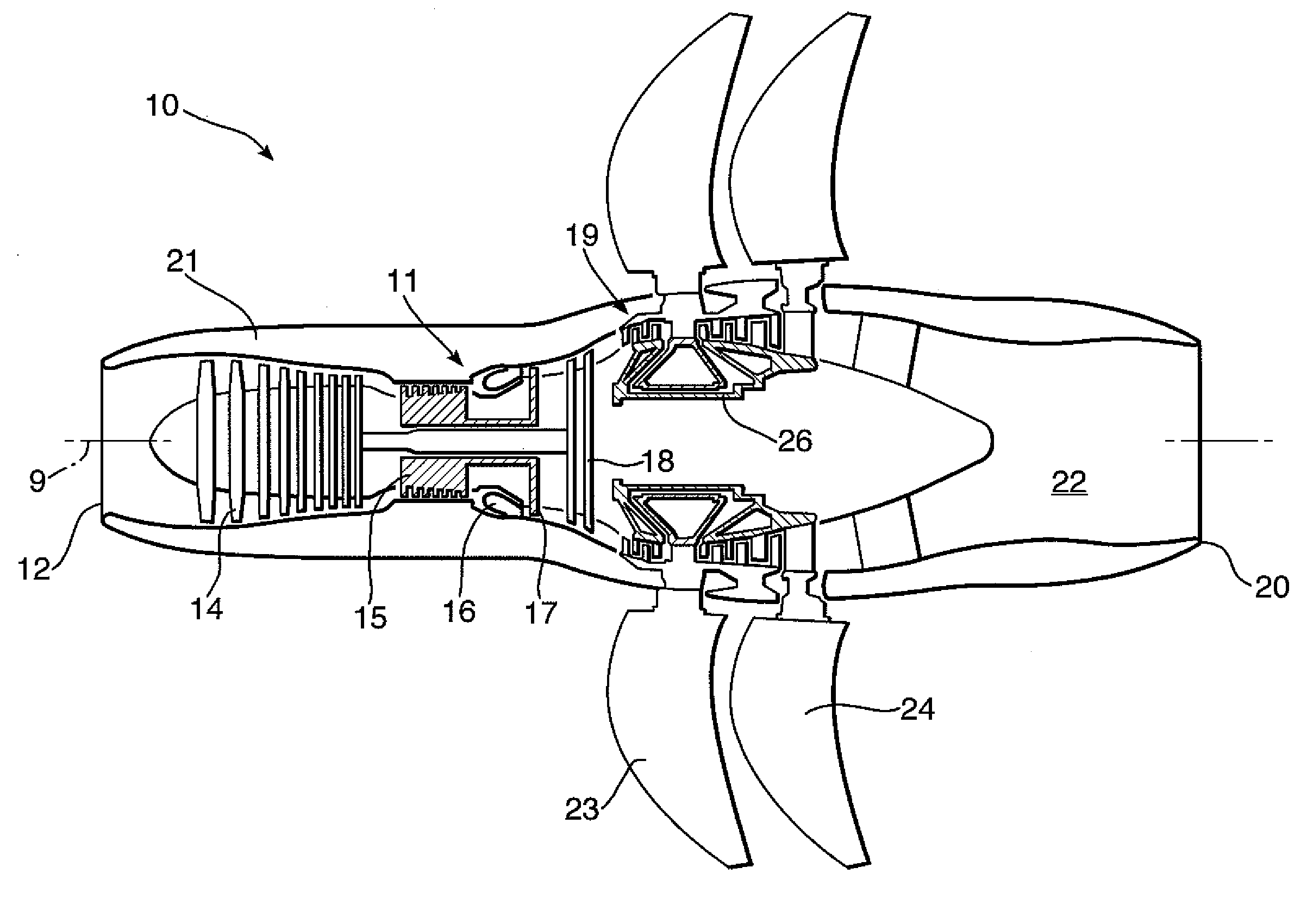
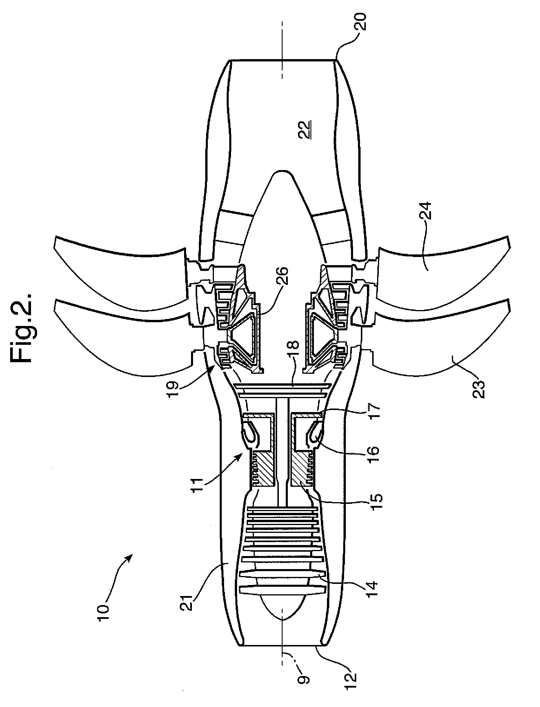
[0024]Referring to FIG. 2, a twin-spooled, contra-rotating propeller gas turbine engine is generally indicated at 10 and has a principal rotational axis 9. The engine 10 comprises a core engine 11 having, in axial flow series, an air intake 12, an intermediate pressure compressor 14, a high-pressure compressor 15, combustion equipment 16, a high-pressure turbine 17, an intermediate pressure turbine 18, a free power (or low-pressure) turbine 19 and a core exhaust nozzle 20. A nacelle 21 generally surrounds the core engine 11 and defines the intake 12 and nozzle 20 and a core exhaust duct 22. The engine 10 also comprises two contra-rotating propeller stages 23, 24 attached to and driven by the free power turbine 19 via shaft 26.

[0025]The gas turbine engine 10 works in a conventional manner so that air entering the intake 12 is accelerated and compressed by the intermediate pressure compressor 14 and directed into the high-pressure compressor 15 where further compression takes place. T...


PUM


Abstract

An engine having at least one stage of propeller rotor blades, and a load, the at least one stage being associated with electrical generation means to generate electricity for the load. The load is switchable into a high load state in the event of an overspeed signal from the rotor blades. Also a method of controlling rotor overspeed of an engine, characterised by the steps of:i. detecting an overspeed signal from the at least one stage, andii. switching the load into a high load state to apply torque to the at least one stage to counteract the overspeed.

Description

CROSS REFERENCE TO RELATED APPLICATION[0001]This application is entitled to the benefit of British Patent Application No. GB 0816636.5, filed on Sep. 12, 2008.FIELD OF THE INVENTION[0002]The present invention relates to controlling rotor overspeed, particularly in relation to an engine comprising variable pitch propeller rotor blade stages.BACKGROUND OF THE INVENTION[0003]A known type of gas turbine engine, particularly for use in aircraft propulsion, is a propeller gas turbine engine or turboprop. This works in conventional form, whereby a core engine comprising compressors, combustion equipment and turbines drives one or more propeller rotor stages via a shaft from a free power, or low-pressure, turbine. The one or more propeller rotor stages may be situated at the front or rear of the engine, where front and rear are defined in terms of the direction of airflow through the engine. The propeller rotor blades extend radially outwardly to describe a larger diameter than the core eng...

Claims


Application Information

Patent Timeline
Patent Type & Authority Applications(United States)
IPC IPC(8): F02D45/00H02P3/22
CPCF01D21/02Y02T50/671F02C9/00B64C11/306B64C11/48B64D27/00B64D35/06B64D2027/005B64D2027/026F05D2270/021Y02T50/40Y02T50/60
Inventor GAINFORD, DAVID MICHAELHOLT, JONATHAN EDMUND
Owner ROLLS ROYCE PLC
Why Eureka
Try Eureka