Fuel cell system programmed to control reactant gas flow in a gas circulation path

Inactive Publication Date: 2009-05-12
HONDA MOTOR CO LTD
View PDF8 Cites 3 Cited by
  • Summary
  • Abstract
  • Description
  • Claims
  • Application Information

AI Technical Summary

Benefits of technology

[0011]The present invention was conceived in view of the above circumstances, and objects thereof are to provide a fuel cell system in which a fuel gas can be efficiently used, and thereby fuel economy can be improved, and to provide an operation method therefor.
[0013]According to the above fuel cell system, even when there is no flow in the circulation path at starting or the like of the fuel cell system, unreacted fuel gas contained in the off-gas can be supplied to the fuel cell by operating the fuel pump in a state in which the discharge valve is closed. In addition, once a flow of the fuel gas is produced in the circulation path by operating the pump, the fuel off-gas in the circulation path can be supplied to the fuel gas supply path by using the ejector. Because the pump is required merely to produce a flow of the fuel gas, the pump may be of a small size, and electrical power for operating the pump can be reduced. As a result, even when there is no flow in the circulation path at starting or the like of the fuel cell system, the fuel gas can be efficiently used without being discharged to the outside, and fuel economy can be improved.
[0015]According to the above fuel cell system, the concentration of the fuel in the off-gas is estimated based on the voltage of the cells measured by the voltage measuring device, and when it is determined that the concentration of the fuel is greater than a predetermined value, the discharge valve is closed so that the off-gas is circulated, and in contrast, when it is determined that the concentration of the fuel is less than the predetermined value, the discharge valve is opened so that the off-gas is discharged. As a result, the fuel contained in the off-gas can be efficiently used. In addition, because the pump is operated only when the concentration of the fuel is greater than a predetermined value, electrical power for operating the pump can be saved, and an efficient operation can be achieved.
[0017]According to the above fuel cell system, the concentration of an impure gas (gas other than the fuel gas, which mainly includes a nitrogen gas) in the fuel off-gas can be estimated depending on the state-of-load of the fuel pump measured by the state-of-load measuring device. As a result, by controlling the discharge valve so as to be opened when the concentration of the impure gas reaches a predetermined concentration, the off-gas having the impure gas at a high concentration can be purged. By the purging operation, high load state of the fuel pump due to the impure gas can be reduced, and the fuel pump can be preferably protected.
[0019]According to the above operation method, at least at starting in which flow is not produced by only using the ejector, because the fuel pump is operated in a state in which the discharge valve is closed so that useless discharge of the fuel due to flow in the circulation path produced by opening the discharge valve can be avoided, the fuel can be efficiently used. By applying this method to a vehicle provided with the fuel cell system, fuel economy can be improved due to efficient use of fuel.

Problems solved by technology

However, in the above-mentioned fuel cell system provided with the ejector, a problem is encountered upon starting the fuel cell system.
When hydrogen is purged from the hydrogen circulation path in order to produce the forced flow, a problem is encountered in that fuel economy is reduced because unreacted hydrogen gas is discharged from the circulation path.
On the other hand, in the above-mentioned fuel cell system provided with the pump or compressor, because the pump or compressor must be continuously operated during circulation of the hydrogen gas, electrical power for operating the pump or compressor is continuously consumed, and thus, a problem is encountered in that fuel economy is reduced by an amount corresponding to the consumed electrical power.

Method used


Image

  • Fuel cell system programmed to control reactant gas flow in a gas circulation path
  • Fuel cell system programmed to control reactant gas flow in a gas circulation path
  • Fuel cell system programmed to control reactant gas flow in a gas circulation path

Examples


Embodiment Construction

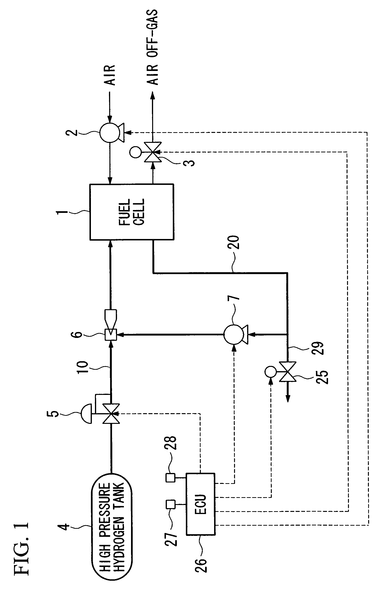
[0030]First, a first embodiment of the fuel cell system according to the present invention will be explained with reference to FIG. 1.

[0031]FIG. 1 is schematic constitution diagram showing the fuel system in the first embodiment.

[0032]A fuel cell 1 is a stack that is formed by stacking a plurality of fuel cell units, each of which includes a solid polymer electrolyte membrane consisting of, for example, a solid polymer ion exchange membrane, and an anode and a cathode that sandwich the solid polymer electrolyte membrane therebetween. When hydrogen as a fuel gas is supplied to the anode, and air containing oxygen as an oxidizing gas is supplied to the cathode, hydrogen ions are produced in the anode area by catalytic reaction, which pass through the solid polymer electrolyte membrane, and which reach the cathode area where the hydrogen ions electrochemically react with oxygen so that electrical power is generated, and water is produced. Because a portion of the water produced in the ...


PUM


Abstract

A fuel cell system includes a fuel cell for generating power by being supplied with a fuel gas and an oxidizing gas, a fuel gas supply path for supplying a fuel gas to the fuel cell, a fuel off-gas circulation path for returning a fuel off-gas discharged from the fuel cell to the fuel gas supply path, an ejector, provided in the fuel gas supply path and driven by fluid flow energy, for supplying the fuel off-gas in the fuel off-gas circulation path flow to the fuel gas supply path, a fuel pump, provided in the fuel off-gas circulation path or on the fuel gas supply path and downstream with respect to the ejector, and driven by a rotating machine, for pressurizing the fuel off-gas, a discharge valve for discharging the fuel off-gas from the fuel off-gas circulation path; and a control device operatively connected to the fuel pump and to the discharge valve.

Description

BACKGROUND OF THE INVENTION[0001]1. Field of the Invention[0002]The present invention relates to a fuel cell system employed in a fuel cell-powered vehicle or the like, and relates to an operation method therefor.[0003]Priority is claimed on Japanese Patent Application No. 2002-332183, filed Nov. 15, 2002, the content of which is incorporated herein by reference.[0004]2. Description of Related Art[0005]As a type of fuel cell to be installed in a fuel cell powered vehicle, a fuel cell is known which includes a fuel cell unit having an anode and a cathode that together sandwich a solid polymer electrolyte membrane therebetween, and in which a fuel gas (e.g., hydrogen gas) is supplied to the anode, and an oxidizing gas (e.g., oxygen or air) is supplied to the cathode so that electrochemical energy produced in an oxidation-reduction reaction of these reaction gases is directly output as electrical energy.[0006]Because an anode off-gas (hereinafter referred to as a hydrogen off-gas) disc...

Claims


Application Information

Patent Timeline
IPC IPC(8): H01M8/04
CPCH01M8/04097H01M8/04223Y02E60/50H01M8/241H01M8/04225H01M8/2457H01M8/2483H01M8/04228
Inventor SUGAWARA, TATSUYAMIYANO, KOUJISHIMANUKI, HIROSHI
Owner HONDA MOTOR CO LTD
Why Eureka
Try Eureka