Overvoltage protection circuit for use in charger circuit system and charge circuit with overvoltage protection function

Inactive Publication Date: 2010-03-18
RICHTEK TECH
View PDF7 Cites 1 Cited by
  • Summary
  • Abstract
  • Description
  • Claims
  • Application Information

AI Technical Summary

Benefits of technology

[0006]An objective of the present invention is to solve the problems of the prior art mentioned above; hence, the present invention provides an improved circuit structure. In one

Problems solved by technology

Accordingly, it has the following drawbacks: first, more cost; second, the two large transistors connected in series in t

Method used


Image

  • Overvoltage protection circuit for use in charger circuit system and charge circuit with overvoltage protection function
  • Overvoltage protection circuit for use in charger circuit system and charge circuit with overvoltage protection function
  • Overvoltage protection circuit for use in charger circuit system and charge circuit with overvoltage protection function

Examples


Example

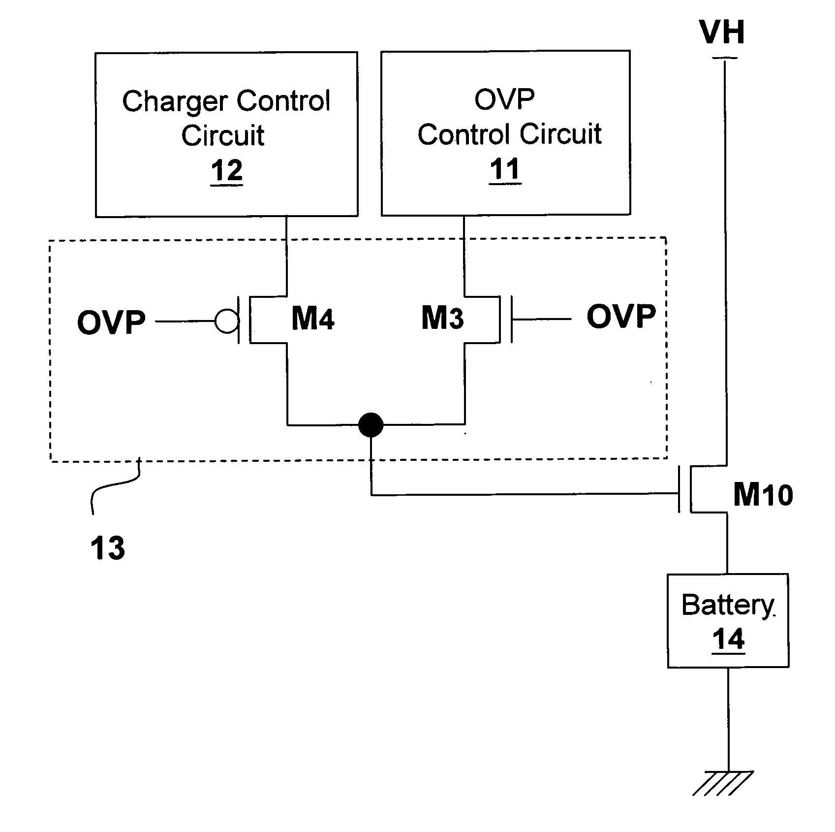
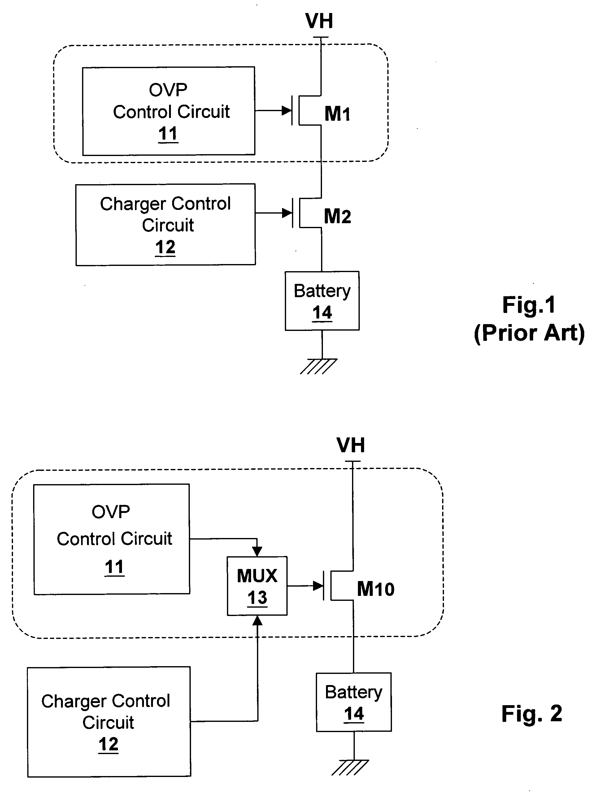
[0016]Referring to FIG. 2 for an embodiment of the present invention, in which only one transistor M10 is provided. The transistor M10 provides dual functions, operating both as an OVP switch while controlled by the OVP control circuit 11, and as a current controller while controlled by the charger control circuit 12. While it operates as an OVP switch, it has two statuses, on and off; while it operates to provide current control function, depending on the design of charger control circuit 12, the transistor M10 may have many analog statuses other than on and off, to control the amount of charge current to the battery 14.

[0017]The outputs of the OVP control circuit 11 and the charger control circuit 12 are electrically connected to a multiplexing circuit MUX 13. The multiplexing circuit MUX 13 selects between the output of the OVP control circuit 11 and the output of the charger control circuit 12, and controls the gate of the transistor M10 thereby. In other words, the output of th...


PUM


Abstract

The present invention discloses an overvoltage protection (OVP) circuit for use in a charger circuit system, comprising: a power transistor electrically connected between a voltage supply and a battery; an OVP circuit which turns off the transistor when a voltage supply exceeds a threshold value; and a multiplexing circuit electrically connected between an output of the OVP circuit and the gate of the transistor. The present invention also discloses a charger circuit with an OVP function, comprising: a single power transistor electrically connected between a voltage supply and a battery; an OVP control circuit which turns off the power transistor when a voltage supply exceeds a threshold value; and a charger control circuit which controls the gate of the power transistor to determine a charge current to the battery when the voltage supply does not reach the threshold value.

Description

BACKGROUND OF THE INVENTION[0001]1. Field of Invention[0002]The present invention relates to an overvoltage protection (OVP) circuit for use in a charger circuit system and a charger circuit with OVP function.[0003]2. Description of Related Art[0004]Please refer to FIG. 1, which shows a prior art charger circuit. In this circuit, the OVP control circuit 11 detects whether the voltage supply VH exceeds a threshold value before charging the battery 14 (this battery for example is a battery in a portable electronic device); the OVP control circuit 11 turns on the transistor switch M1 only when the voltage supply VH is within a safety range, so that the battery can be safely charged. The OVP control circuit 11 and the transistor switch M1 can be taken combinationally as an OVP circuit (as shown in the dotted line). In charging process, the charger control circuit 12 controls the gate voltage of the transistor M2 to determine the amount of the charging current.[0005]The prior art shown i...

Claims


Application Information

Patent Timeline
IPC IPC(8): H02J7/04
CPCH02J7/0031H02J7/00308
Inventor LU, CHIEN-PINGKUNG, NIEN-HUILEE, LI-WEICHU, KWAN-JENHSING, YING-HSINCHEN, CHUN-TSUNG
Owner RICHTEK TECH
Why Eureka
Try Eureka