

Circuit structure for rechargeable battery
- Summary
- Abstract
- Description
- Claims
- Application Information
AI Technical Summary
Benefits of technology
Problems solved by technology
Method used
Image

Examples
Embodiment Construction
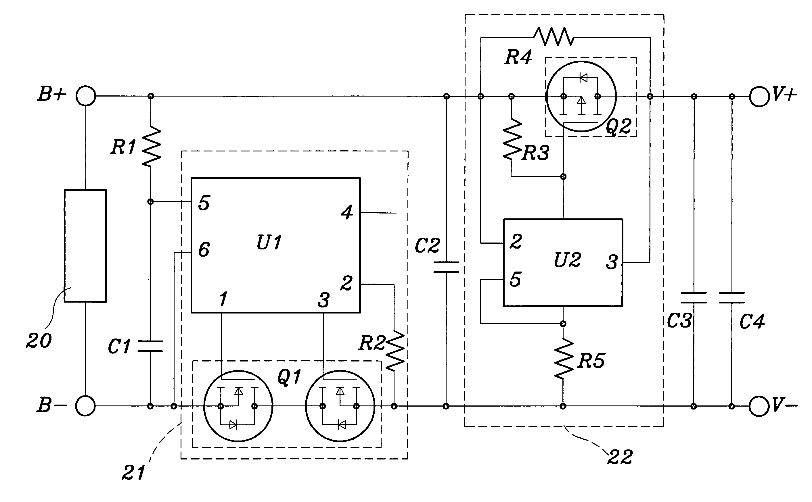
[0018] Referring to FIG. 3, in the preferred practicable embodiment, the present invention is provided in a charging electric circuit device thereof for a battery 20 with a detective protecting electric circuit 21 and a charging-discharging electric circuit 22. The detective protecting electric circuit has 21 a protective integrated circuit (IC) U1 and a protective circuit switch Q1; the charging-discharging electric circuit 22 has a voltage stabilizing integrated circuit (IC) U2 and a voltage stabilizing circuit switch Q2 connecting with the voltage stabilizing integrated circuit (IC) U2. The voltage stabilizing integrated circuit (IC) U2 stabilizes the voltage of the battery 20 at a set value (such as 3.0 volts).
[0019] As shown in FIG. 4, when the circuit structure of the present invention uses a charger 23 for electric charging, the protective integrated circuit (IC) U1 detects at B+ and B−, when the voltage of the battery 20 exceeds the set value (such as 4.25 volts), the prote...
PUM
 Abstract
Description
Claims
Application Information