Systems for measuring backscattered light using finite speed of light

a technology of backscattered light and finite speed, applied in the direction of distance measurement, instruments, material analysis, etc., can solve the problems of affecting the interpretation of information that is retrieved, increasing the signal intensity of the detector, and ray interference with each other

Inactive Publication Date: 2010-03-18
UNITED STATES OF AMERICA THE AS REPRESENTED BY THE SEC OF THE ARMY
View PDF27 Cites 16 Cited by
  • Summary
  • Abstract
  • Description
  • Claims
  • Application Information

AI Technical Summary

Problems solved by technology

In addition, multiple scattering of rays by points on the object causes the rays to interfere with each other.
In the backscatter region, rays that travel reciprocal paths interfere constructively, resulting in an increase in signal intensity on the detector.
Most remote-measuring techniques like LIDAR do not measure light in the exact backscatter direction (β=0), so it is difficult to interpret the information that is retrieved.

Method used


Image

  • Systems for measuring backscattered light using finite speed of light
  • Systems for measuring backscattered light using finite speed of light
  • Systems for measuring backscattered light using finite speed of light

Examples


Embodiment Construction

[0014]Systems for measuring backscattered light are provided, and several exemplary embodiments will be discussed in detail. In this regard, embodiments may be used for measuring the spatial relationship between objects at a distance. Additionally or alternatively, some embodiments may be used to provide information about the size distribution and / or chemical properties of particles in a sample.

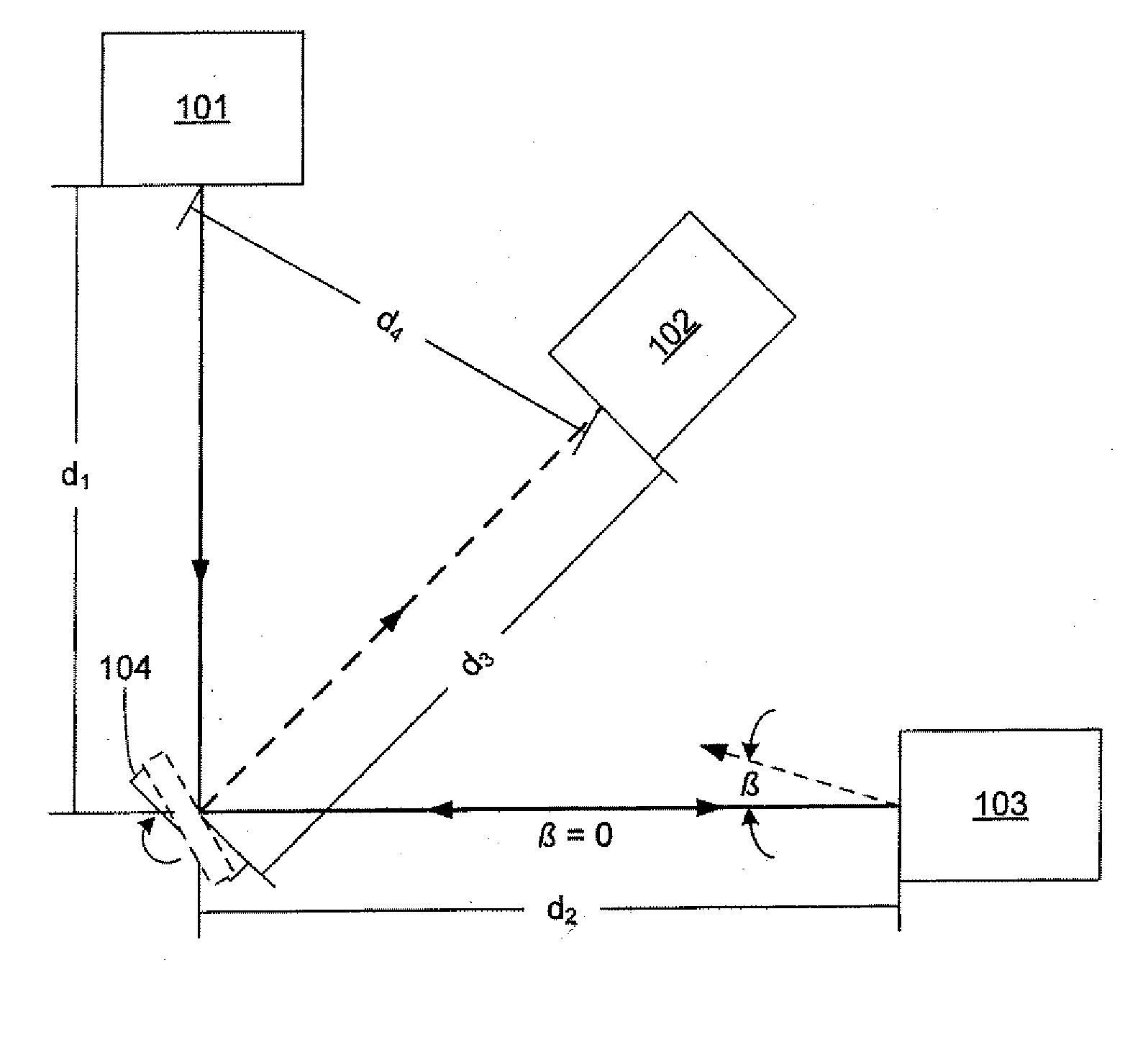
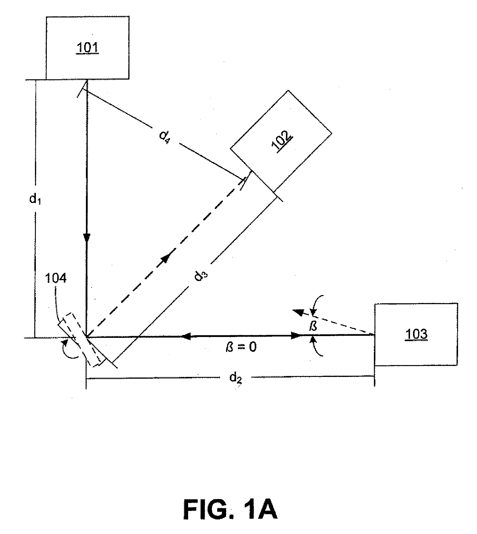
[0015]FIG. 1A shows an exemplary embodiment of a system for measuring backscattered light that incorporates a light source 101, a rotating mirror 104, and a detector 102. The mirror 104 rotates at a rotational frequency f. Light from the source 101 is directed to the mirror 104, which reflects the light toward a sample 103. The sample 103 scatters the light. The exactly backscattered (β=0) light propagates back toward the mirror 104. During the time interval in which the light propagates to the sample and back to the mirror, mirror 104 has rotated. Thus, the mirror is positioned to reflect th...


PUM

PropertyMeasurementUnit
rotational frequencyaaaaaaaaaa
phase lagaaaaaaaaaa
sizeaaaaaaaaaa

Abstract

A system for measuring backscattered light from a sample is given. Light is output from a light source towards a rotating mirror, and then reflected by the rotating mirror towards the sample. The sample reflects backscattered light back towards the rotating mirror, which, having moved during the time it took for the light to propagate from the mirror to the sample and back, reflects the backscattered light to a detector located at a physical separation from the light source. The detected backscattered light may be analyzed to determine various properties of the sample.

Description

GOVERNMENT INTEREST[0001]The invention described herein may be manufactured, used, and licensed by or for the United States Government.BACKGROUND[0002]1. Technical Field[0003]The disclosure generally relates to light scattering, detection, and characterizing particle systems.[0004]2. Description of the Related Art[0005]Light scattering can provide a non-destructive means of obtaining information about an object from a distance. As use herein, the term “light” refers to electromagnetic radiation over the entire electromagnetic spectrum including, but not limited to, visible light, ultraviolet light, infrared light, and near infrared light. The object can be a surface, like that of the Earth observed from space or of a computer wafer in a clean-room environment. The object can also be a cloud consisting of smoke, ice crystals, pollutants, biological agents, or any number of other things about which information is desired. In many scattering configurations, the light source and detecto...

Claims


Application Information

Patent Timeline
Patent Type & Authority Applications(United States)
IPC IPC(8): G01N21/47
CPCG01N15/0205G01N21/21G01N21/47G01N21/53G01N2201/105G01N2015/03G01N2021/4709G01N2201/0697G01N21/9501
Inventor VIDEEN, GORDEN W.MUINONEN, KARRI OLAVI
Owner UNITED STATES OF AMERICA THE AS REPRESENTED BY THE SEC OF THE ARMY
Why Eureka
Try Eureka