Vehicle headlamp

a headlamp and projector technology, applied in the field of projector-type vehicle headlamps, can solve problems such as visibility problems, and achieve the effects of improving visibility, simplifying structure, and contributing to traffic safety

Active Publication Date: 2010-03-18
ICHIKOH IND LTD
View PDF17 Cites 18 Cited by
  • Summary
  • Abstract
  • Description
  • Claims
  • Application Information

AI Technical Summary

Benefits of technology

[0073]According to a vehicle headlamp of the present invention, when a semiconductor-type light source is lit to emit light, the light from the semiconductor-type light source is reflected on a main reflecting surface and a first auxiliary reflecting surface. A part of the light reflected from the main reflecting surface is shaded by means of a shade, and a remaining part of the reflected light is projected (illuminated) forwardly from a projecting lens as a light distribution pattern having a cutoff line. In addition, a part of the light reflected from the first auxiliary reflecting surface is reflected on a second auxiliary reflecting surface, and is forwardly projected (illuminated) as a light distribution pattern for overhead sign from the projecting lens. Further, another part of the light reflected from the first auxiliary reflecting surface is reflected on a third auxiliary reflecting surface and the light reflected from the third auxiliary reflecting surface is forwardly projected (illuminated) as an auxiliary light distribution pattern, from the projecting lens between a light distribution pattern having a cutoff line and a light distribution pattern for overhead sign. In this manner, the vehicle headlamp according to the first aspect of the present invention becomes capable of distributing an auxiliary light distribution pattern between the light distribution pattern having the cutoff line and the distribution pattern for overhead sign. As a result, the vehicle headlamp according to the first aspect of the present invention becomes capable of, by means of the auxiliary light distribution pattern, eliminating a dark matter exerted by optical dropout(s) between the cutoff line of the light distribution pattern and the light distribution pattern for overhead sign, thus making it possible to improve visibility and contribute to traffic safety.
[0074]In addition, according to the vehicle headlamp of the present invention, the reflected light that is not shaded by means of the shade from the main reflecting surface, passing through a space at the shading side of the shade on a meridional image of the projecting lens, is projected (illuminated) forwardly from the projecting lens, as a light distribution pattern having a cutoff line. In addition, light reflected from a second auxiliary reflecting surface, passing through a cutout portion at a side opposite to the shading side of the shade on the meridional image face of the projecting lens, is projected (illuminated) forwardly from the projecting lens, as a light distribution pattern for overhead sign. Further, light reflected from a fourth auxiliary reflecting surface, passing through a cutout portion at a side opposite to the shading side of the shade on the meridional image face of the projecting lens, is projected (illuminated) as an auxiliary light distribution pattern forwardly from the projecting lens between the light distribution pattern having the cutoff line and the light distribution pattern for overhead sign. In this manner, the vehicle headlamp according to the first aspect of the present invention becomes capable of reliably distributing the auxiliary light distribution pattern having the cutoff line and the light distribution pattern for overhead sign with a simplified structure. As a result, the vehicle headlamp according to the first aspect of the present invention becomes capable of, by means of the auxiliary light distribution pattern, eliminating a dark matter exerted by optical dropout(s) between the cutoff line of the light distribution pattern and the light distribution pattern for overhead sign, thus making it possible to improve visibility and contribute to traffic safety.

Problems solved by technology

However, the conventional vehicle headlamp entails a problem concerning visibility, which could arise due to the fact that a dark matter exerted by optical dropout(s) takes place between a light distribution pattern for passing, having a cutoff line, and a light distribution pattern for overhead sign.

Method used


Image

  • Vehicle headlamp
  • Vehicle headlamp
  • Vehicle headlamp

Examples


Embodiment Construction

)

[0082]Hereinafter, an embodiment of a vehicle headlamp according to the present invention will be described in detail referring to the drawings. This embodiment does not limit the present invention.

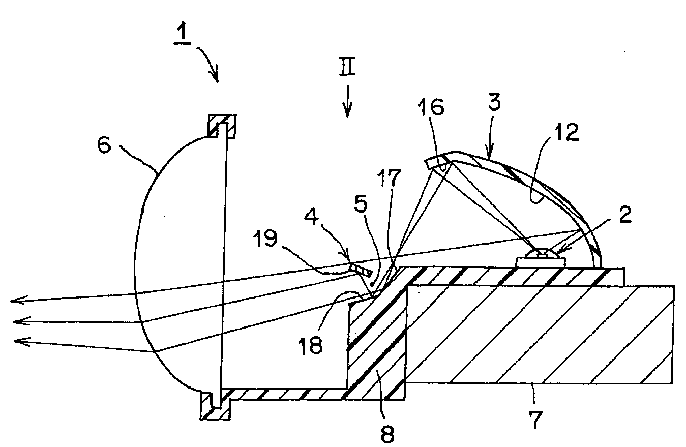
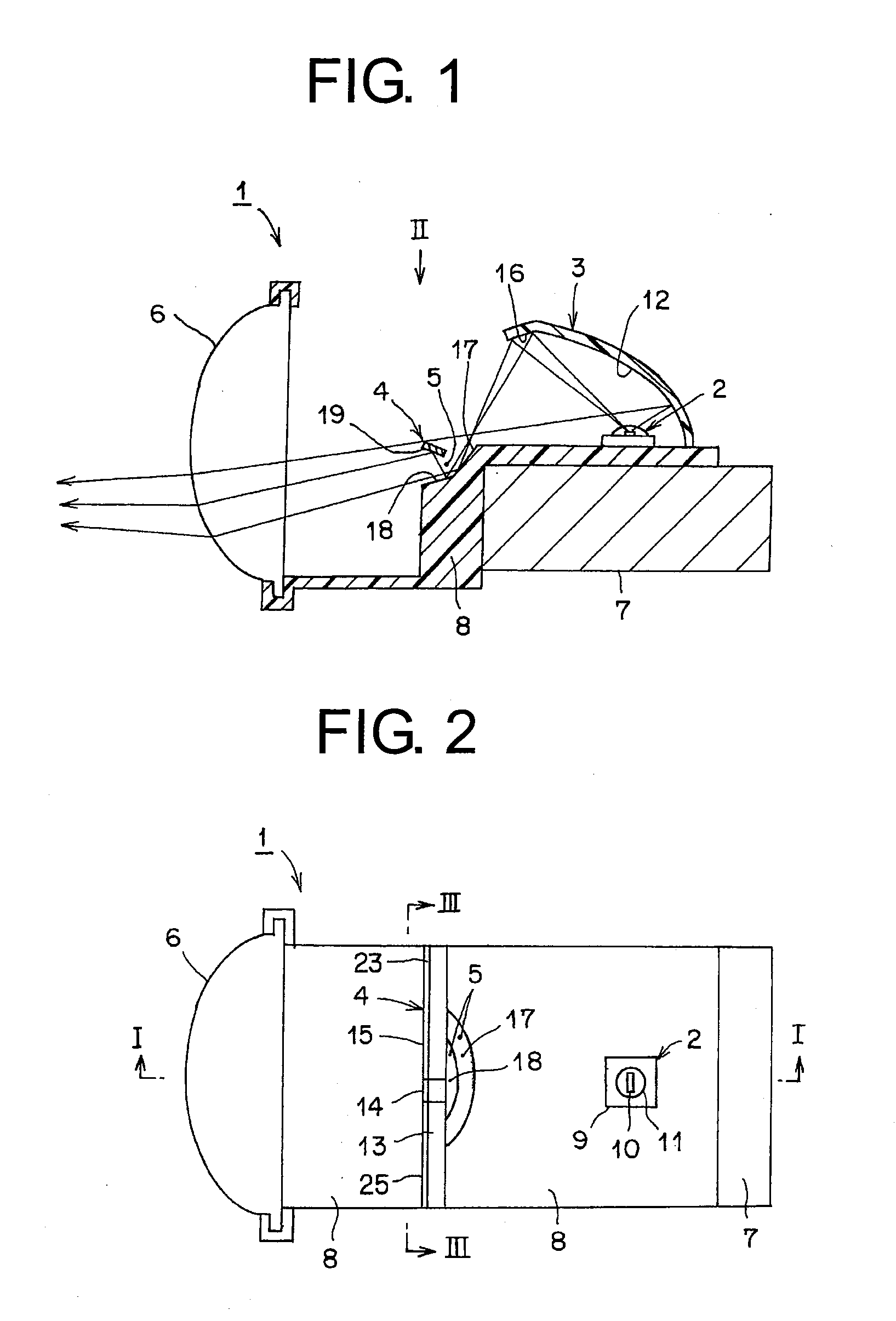
[0083]First, a configuration of the vehicle headlamp in the embodiment will be described hereinafter. In FIG. 1, reference numeral 1 designates the vehicle headlamp in the embodiment. The vehicle headlamp 1 is of projector type, and forms a unitary structure. The vehicle headlamp 1 is made up of: a semiconductor-type light source 2; a reflector 3; a shade 4; a projecting lens 6; a heat sink member 7; a holding member 8; and a lamp housing and a lamp lens of the vehicle headlamp (such as a transparent outer lens, for example), although not shown.

[0084]The semiconductor-type light source 2, the reflector 3, the shade 4, the projecting lens 6, the heat sink member 7, and the holding member 8 constitute a lamp unit. The lamp unit is disposed in one or plurality via an optical-axis adjustment...


PUM


Abstract

A vehicle headlamp of the present invention is provided with: a semiconductor-type light source; a main reflecting surface; a first auxiliary reflecting surface; a shade; a second auxiliary reflecting surface; a third auxiliary reflecting surface; and a fourth auxiliary reflecting surface. The shade forms a light distribution pattern for passing, having cutoff lines. The first auxiliary reflecting surface and the second auxiliary surface form a light distribution pattern for overhead sign. The first auxiliary reflecting surface, the third auxiliary reflecting surface, and the fourth auxiliary reflecting surface form an auxiliary light distribution pattern between the light distribution pattern for passing, having the cutoff lines, and a light distribution pattern for overhead sign. As a result, the vehicle headlamp of the present invention improves visibility.

Description

CROSS REFERENCE TO RELATED APPLICATIONS[0001]This application claims priority of Japanese Patent Application No. 2008-238245 filed on Sep. 17, 2008. The contents of this application are incorporated herein by reference in their entirety.BACKGROUND OF THE INVENTION[0002]1. Field of the Invention[0003]The present invention relates to a projector-type vehicle headlamp using a semiconductor-type light source such as an LED, for example, as a light source.[0004]2. Description of the Related Art[0005]A vehicle headlamp of this type is conventionally known (Japanese Laid-open Patent Application No. 2008-41271, for example). Hereinafter, the conventional vehicle headlamp will be described. The conventional vehicle headlamp is provided with: a light source; a first reflecting surface for reflecting light from the light source on a first illumination region; a light shading member for shading a part of the light reflected from the first reflecting surface; a second reflecting surface for refl...

Claims


Application Information

Patent Timeline
Patent Type & Authority Applications(United States)
IPC IPC(8): B60Q1/04
CPCB60Q1/076F21S41/148F21S41/365F21S41/43F21W2102/18
Inventor SUZUKI, YASUFUMI
Owner ICHIKOH IND LTD
Why Eureka
Try Eureka