Supercharge Your Innovation With Domain-Expert AI Agents!

Code division multiplex signal transmitter and code division multiplexing method with amplifying circuits reduced in number

a code division multiplex and code division technology, applied in multiplex communication, digital transmission, electrical equipment, etc., can solve the problems of increasing increasing the cost of components, increasing the size of circuitry in multiplexers, etc., to reduce the cost of components and reduce the number of amplifying circuits. , the effect of reducing the number of amplifying circuits

Inactive Publication Date: 2010-03-18
OKI ELECTRIC IND CO LTD
View PDF7 Cites 2 Cited by
  • Summary
  • Abstract
  • Description
  • Claims
  • Application Information

AI Technical Summary

Benefits of technology

The present invention provides a CDM signal transmitter with reduced costs and size by decreasing the number of amplifying circuits. This is achieved by adding up N channels of data to produce added data, and then amplifying the output data. The added data is compared with threshold values to select the appropriate output data. The CDM method also reduces the number of necessary amplifying circuits. Overall, the invention provides a more efficient and cost-effective solution for CDM signal transmission.

Problems solved by technology

Therefore, an increase in the number N of the channels leads to an increase in number of amplifying circuits, thus increasing the cost for the components.
In addition, it increases the size of circuitry in the multiplexer so that it is difficult to manufacture it.

Method used


Image

  • Code division multiplex signal transmitter and code division multiplexing method with amplifying circuits reduced in number
  • Code division multiplex signal transmitter and code division multiplexing method with amplifying circuits reduced in number
  • Code division multiplex signal transmitter and code division multiplexing method with amplifying circuits reduced in number

Examples


Embodiment Construction

[0029]A preferred embodiment in accordance with the present invention will be described below with reference to the accompanying drawings. In the drawings, the components and elements are merely schematically depicted to the extent that the present invention can be appreciated. Preferred exemplary configurations of the present invention will be described below, but are merely preferred examples. Therefore, the present invention is not to be restrictively comprehended by the following embodiment. The embodiment can be variously changed or modified so as to provide advantages of the present invention without departing from the scope and spirit of configurations of the present invention.

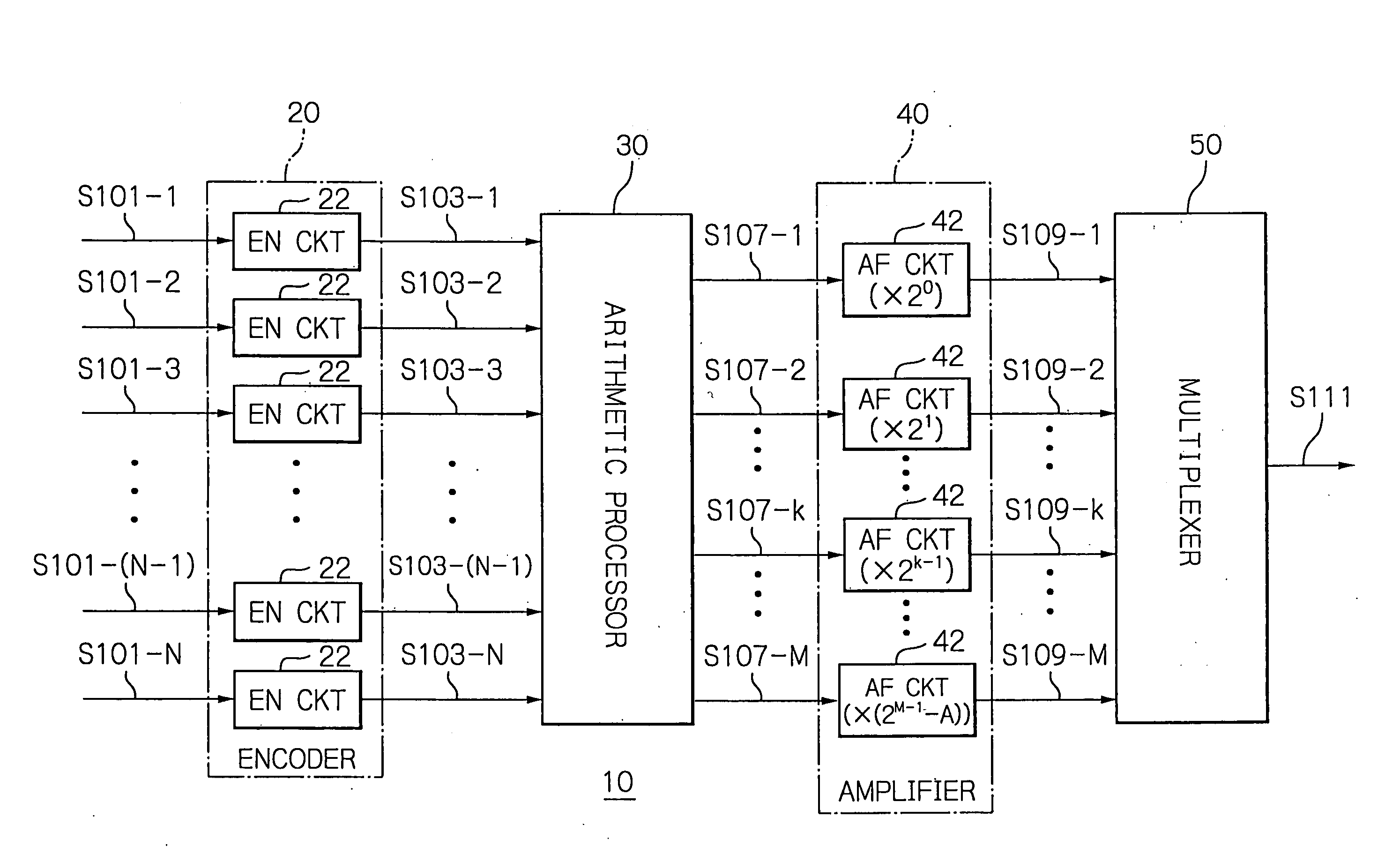
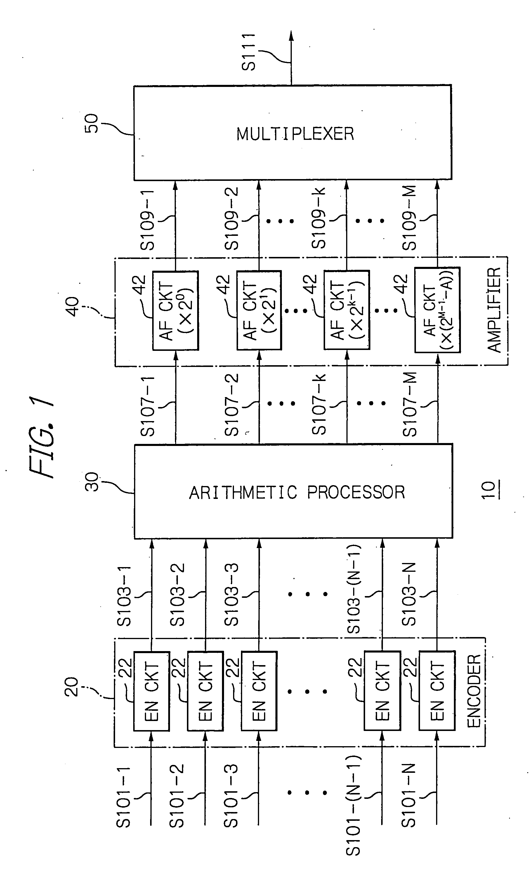
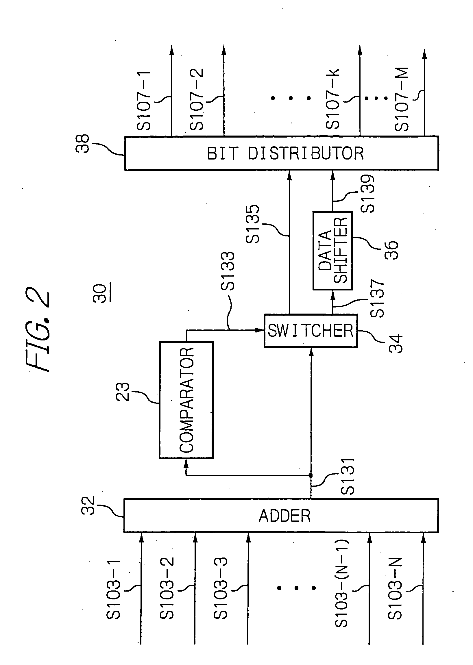
[0030]With reference to FIGS. 1 and 2, a Code Division Multiplexing (CDM) signal transmitter 10 in accordance with the present invention will be described. FIG. 1 is a schematic diagram showing an exemplified configuration of the CDM signal transmitter 10 in accordance with the present invention. FIG. 2...


PUM


Abstract

N channels of encoded data are added into added data, which is compared with a first threshold of 2M−1−A and a second threshold of 2M−1−1, where M is the number of the bit positions of the binary representation of N and A is defined by 2M−(N+1). When the added data is less than the first threshold, it is selected. When the added data falls between the first and second thresholds, inclusive, either the added data or shifted data, obtained by adding A to the added data, is selected. When the added data exceeds the second threshold, the shifted data is selected. Based on output data representing the values of the respective bit positions of the binary representation of the selected data, the k-th output data, where k is a natural number less than M, is amplified into k-th amplified data having an amplitude level of 2k−1, and the M-th output data is amplified into M-th amplified data having an amplitude level of 2M−1−A. The first to M-th amplified data are multiplexed into a CDM signal.

Description

BACKGROUND OF THE INVENTION[0001]1. Field of the Invention[0002]The present invention relates to a code division multiplex signal transmitter and a code division multiplexing method for use in a transmission side of code division multiplex communication.[0003]2. Description of the Background Art[0004]Code division multiplexing (CDM) technology is used for a telecommunications network system, which can multiplex a plurality of data to be transmitted in a time slot. Since the CDM technology can be used to transmit a large amount of data while saving a communications resource such as time slots, it has mainly been put to practical use for mobile communications.[0005]With reference to FIG. 12, an exemplified conventional CDM signal transmitter for use in CDM communication will be described. FIG. 12 is a schematic block diagram showing the exemplified conventional CDM signal transmitter disclosed in U.S. patent application publication No. US 2004 / 0047330 A1 to Matsuno et al., for example...

Claims


Application Information

Patent Timeline
Patent Type & Authority Applications(United States)
IPC IPC(8): H04J13/00H04B1/707H04J13/16
CPCH04J13/00
Inventor TAMAI, HIDEAKI
Owner OKI ELECTRIC IND CO LTD
Features
  • R&D
  • Intellectual Property
  • Life Sciences
  • Materials
  • Tech Scout
  • Unparalleled Data Quality
  • Higher Quality Content
  • 60% Fewer Hallucinations
Learn More