Fuel cell system

Active Publication Date: 2010-03-18
TOYOTA JIDOSHA KK
View PDF2 Cites 4 Cited by
  • Summary
  • Abstract
  • Description
  • Claims
  • Application Information

AI Technical Summary

Benefits of technology

[0006]Accordingly, to solve the problem described above, an object of the present invention is to provide a fuel cell system which has high operating efficiency and does not develop a physical failure by matching an output current / output voltage characteristic of a fuel cell and a maximum output characteristic of a load.
[0025]Setting the condition as described above makes it possible to presume a case where a maximal point is held between discrete points, allowing proper interpolation calculation to be carried out.

Problems solved by technology

Meanwhile, a fuel cell has an output current / output voltage characteristic while a load has a maximum output characteristic which defines the relationship between an input current and a maximum output, so that matching these two has been a challenge.
However, conventional fuel cell systems have not yet met the challenge.
A failure to match the two causes, for example, a failure to satisfy a maximum output required by a load or an excessive power which is larger than the maximum output required by the load to be supplied from the fuel cell system, resulting in an inconvenience (heat generation, disturbed power balance, or overcharge of a secondary battery) or the like in the fuel cell system.

Method used


Image

  • Fuel cell system
  • Fuel cell system
  • Fuel cell system

Examples


first embodiment

[0038]The embodiments of the present invention are the cases where the present invention has been applied to an electric car equipped with a hybrid fuel cell. The following embodiments are merely examples of applications of the present invention and shall not restrict the present invention.

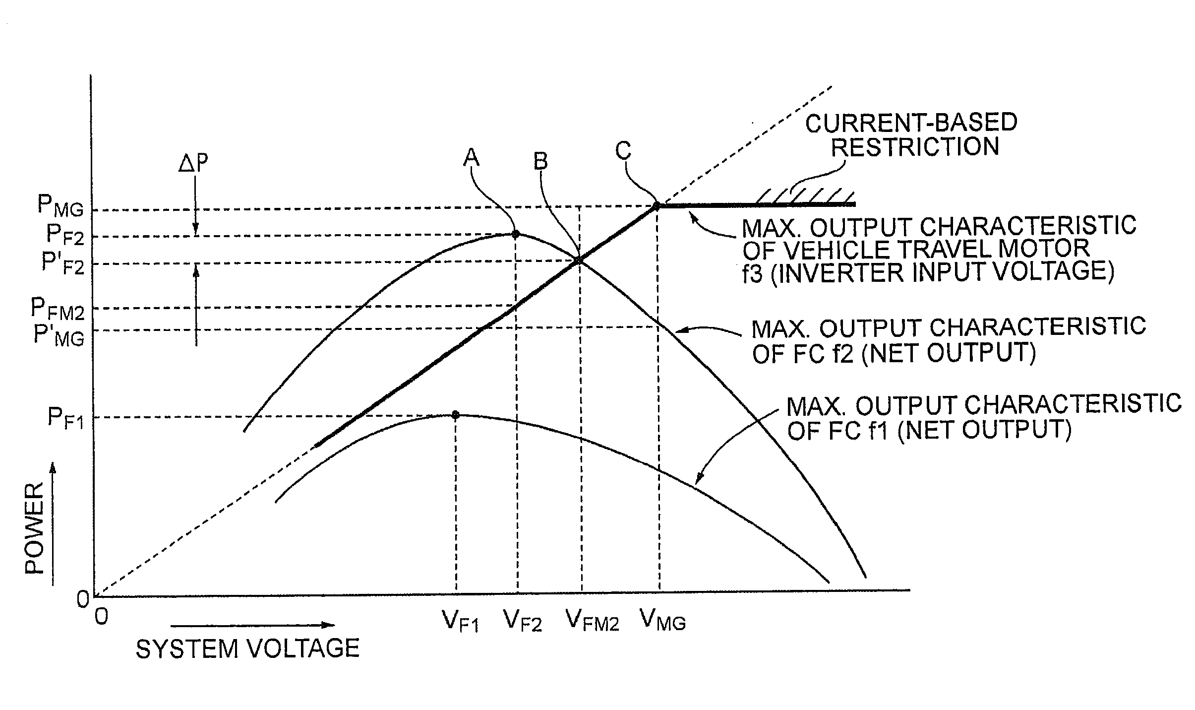
[0039]In the first embodiment, an operating point for outputting an optimum maximum output power is determined on the basis of an output current / output power characteristic of a fuel cell and a maximum output characteristic in a load device.

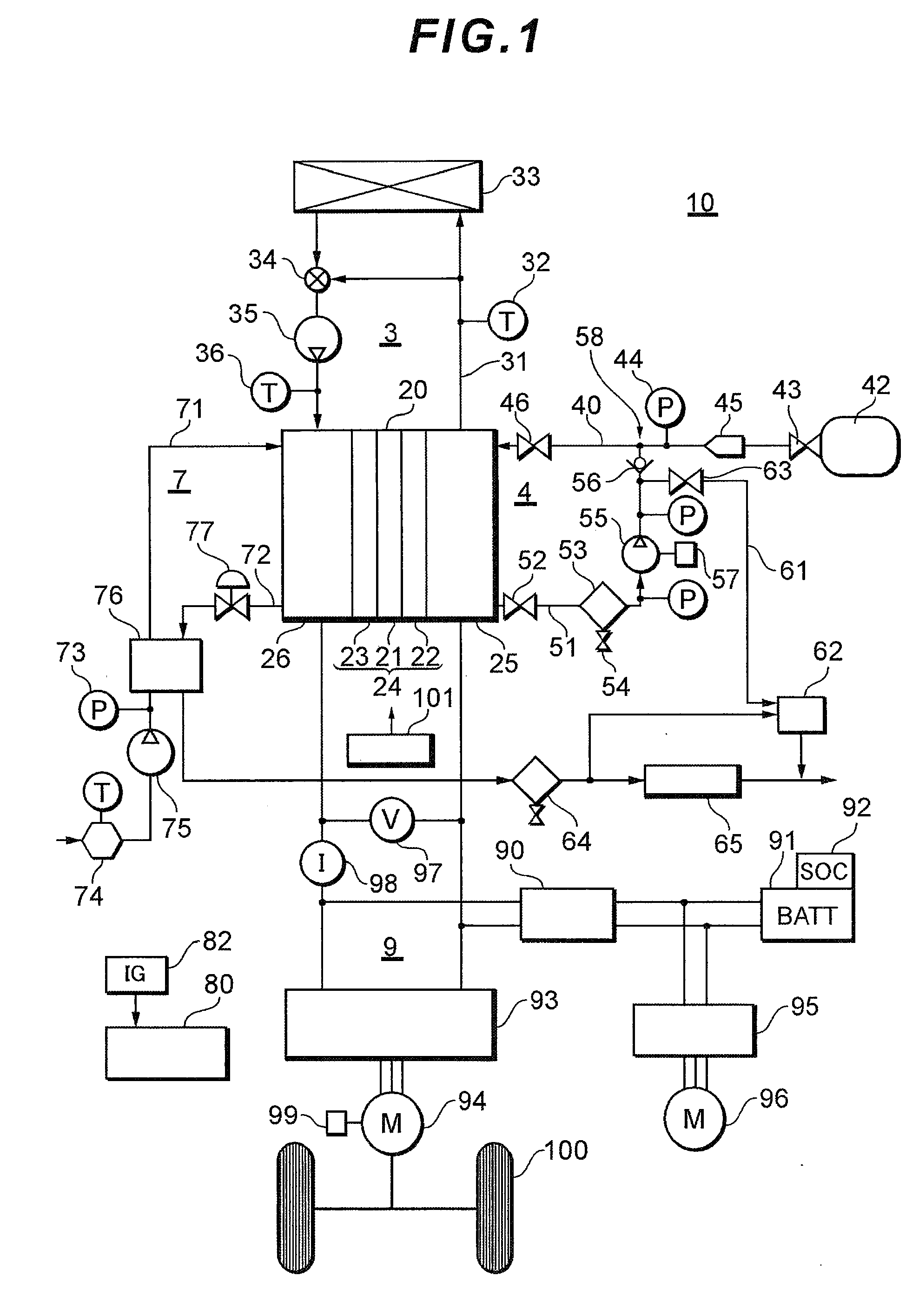
[0040]FIG. 1 is a system block diagram of a fuel cell system to which the present invention has been applied.

[0041]In FIG. 1, a fuel cell system 10 includes, as main constituent elements, a fuel gas supply system 4 for supplying a fuel gas (hydrogen gas) to a fuel cell 20, an oxidizing gas supply system 7 for supplying an oxidizing gas (air) to the fuel cell 20, a coolant supply system 3 for cooling the fuel cell 20, and a power system 9 for charging / dischargin...

second embodiment

[0079]A second embodiment of the present invention relates to an example in which, in a system having the output current (voltage) / output power characteristic of a fuel cell stored in the form of discrete values, an interpolation point providing a maximum output power which lies between adjoining discrete points is determined.

[0080]The fuel cell system in the present embodiment is the same as that in the first embodiment described above, so that the explanation thereof will be omitted.

[0081]In some systems, the maximum output characteristic of the FC and the maximum output characteristic of a load device retained by a control unit 80 are tabled and stored in the form of a discrete map represented by several points on the curves rather than being given in the form of the continuous curves in FIG. 3. In such a system, an operating point to be determined may lie between two discrete points, and it is necessary to prepare an interpolation expression for the discrete points to determine ...


PUM


Abstract

A system voltage indicated by an intersection of a graph of an FC maximum output characteristic of the output voltage / output power characteristic of a fuel cell and a graph of a load device maximum output characteristic is output so as to obtain optimal output power, thereby matching an output current-output voltage characteristic of a fuel cell and a maximum output characteristic of a load. Thus, a fuel cell system which has high operating efficiency and which is free of physical failures is provided.

Description

TECHNICAL FIELD [0001]The present invention relates to a fuel cell system and more particularly to a control method of a fuel cell system mounted in a vehicle (mobile body).BACKGROUND ART [0002]In recent years, a fuel cell system which supplies power to a load, such as a mobile body, is reaching the phase of practical use. A fuel cell is adapted to take out an electromotive force by an electrochemical reaction between a fuel gas, such as hydrogen, and an oxidizing gas which contains oxygen. There is a predetermined relationship between an output current and an output voltage (an output current / output voltage characteristic). Such an output current / output voltage characteristic changes according to, for example, the gas amount of a fuel gas or an oxidizing gas supplied to the fuel cell. Further, on any output current / output voltage characteristic, an output current value which provides a maximum output power (net output) has been set. Here, the output power (allowed FC power) is a ph...

Claims


Application Information

Patent Timeline
IPC IPC(8): H01M8/00H01M8/04
CPCH01M8/04544Y02E60/50H01M8/04865H01M8/04604
Inventor IMAI, ATSUSHIUMAYAHARA, KENJI
Owner TOYOTA JIDOSHA KK
Why Eureka
Try Eureka