Non-Contact ultrasonic tonometer

a tonometer and non-contact technology, applied in the field of non-contact ultrasonic tonometers, can solve problems such as difficulty in precisely measuring intraocular pressure, and achieve the effect of accurately measuring intraocular pressur

Inactive Publication Date: 2010-03-18
NIDEK CO LTD
View PDF11 Cites 10 Cited by
  • Summary
  • Abstract
  • Description
  • Claims
  • Application Information

AI Technical Summary

Benefits of technology

[0005]The present invention has a purpose to provide a non-contact ultrasonic tonometer capable of accurate

Problems solved by technology

However, in the above system, a working distance of an apparatus from the eye (the eyeball model) is short and hence the apparatus may touch an examinee

Method used


Image

  • Non-Contact ultrasonic tonometer
  • Non-Contact ultrasonic tonometer
  • Non-Contact ultrasonic tonometer

Examples


Embodiment Construction

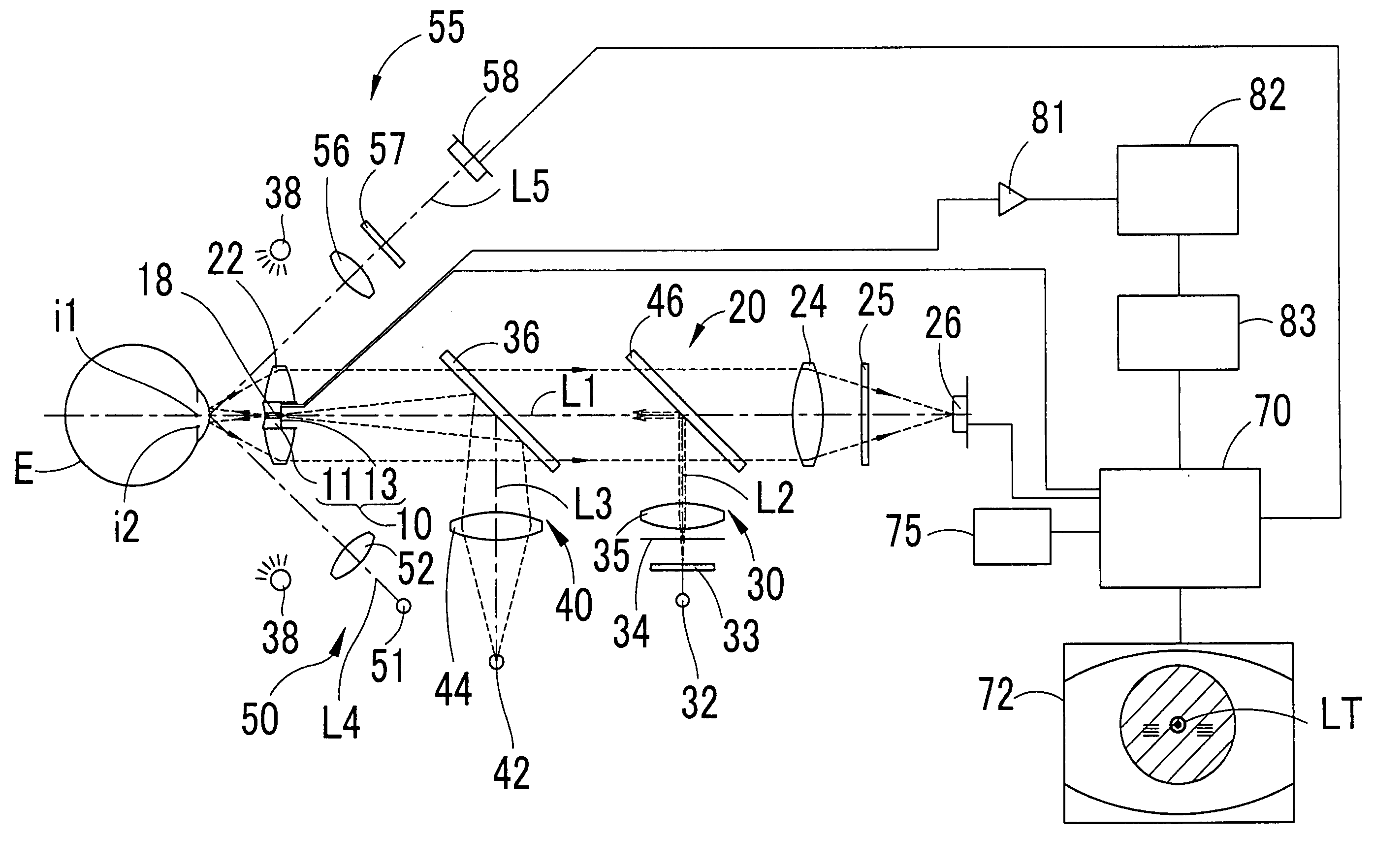
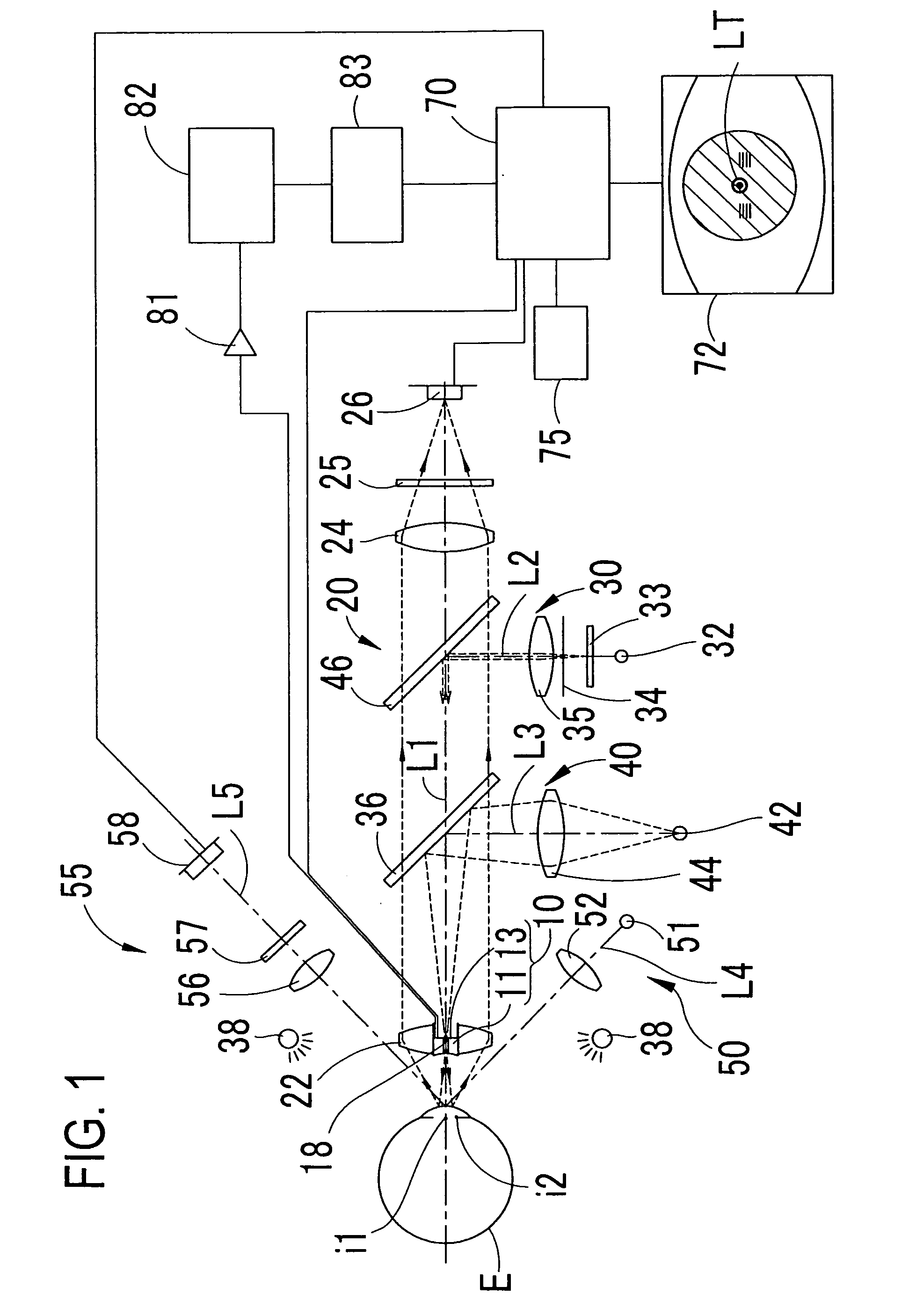
[0011]Towards the practical use of a non-contact ultrasonic tonometer, the present inventors had studied a probe capable of detecting a reflected wave from a cornea with high sensitivity and ensuring that a working distance of an apparatus (the probe) from an examinee's eye is at least 10 mm or longer. A main purpose thereof is to enhance measurement accuracy of intraocular pressure and ensure safety of an examinee's eye.

[0012]The inventors first tried to use a ceramic piezoelectric probe (a piezoelectric element type probe) well known as an ultrasonic probe. However, every ceramic piezoelectric probe could not avoid attenuation of ultrasonic wave in air, inevitably resulting in low detection sensitivity to the reflected wave from the cornea. Furthermore, the attenuation of ultrasonic wave in air becomes larger as the working distance of the apparatus from the examinee's eye is longer. Therefore, it was practically difficult to obtain high measurement precision while ensuring a work...


PUM


Abstract

A non-contact ultrasonic tonometer for measuring intraocular pressure of an examinee's eye in a non-contact manner by use of an ultrasonic wave comprises: a probe that emits an ultrasonic beam to be allowed to enter the eye and detects the ultrasonic beam reflected by the eye; and an arithmetic section that determines the intraocular pressure by processing an output signal from the probe, the probe including a broadband air-coupled transducer that transmits and receives the ultrasonic beam having a broadband frequency component.

Description

TECHNICAL FIELD[0001]The non-contact ultrasonic tonometer for measuring intraocular pressure of an examinee's eye in a non-contact manner by ultrasound (an ultrasonic wave).BACKGROUND ART[0002]There is proposed a non-contact intraocular pressure measurement system including a probe which emits an ultrasonic wave to be allowed to enter an eye (actually, an eyeball mode) and detects the ultrasonic wave reflected by the eye, the system being adapted to measure intraocular pressure of the eye based on a detection result of the probe (see “Development of a new non-contact intraocular pressure measurement system using a phase shift method”, Masayuki JINDE and other three persons, Conference of Institute of Electrical Engineers, Sensors and Micromachines Division, Document p. 93-96, 2007).[0003]However, in the above system, a working distance of an apparatus from the eye (the eyeball model) is short and hence the apparatus may touch an examinee's eye when the intraocular pressure of the hu...

Claims


Application Information

Patent Timeline
IPC IPC(8): A61B3/16
CPCA61B8/10A61B3/165A61B3/152
Inventor JINDE, MASAYUKIMIWA, TETSUYUKIMAKINO, KENICHIRO
Owner NIDEK CO LTD
Why Eureka
Try Eureka