Dynamic fixation system

a dynamic fixation system and dynamic technology, applied in the field of dynamic spinal fixation system, can solve the problems of inability instabilities of the motion segments of the spine, and the rods of the existing dynamic fixation system generally lack the strength and/or constraints to overcome expected shear stress, etc., to achieve the effect of facilitating movemen

Active Publication Date: 2010-03-18
DEPUY SYNTHES PROD INC
View PDF102 Cites 68 Cited by
  • Summary
  • Abstract
  • Description
  • Claims
  • Application Information

AI Technical Summary

Benefits of technology

[0021]In another embodiment, the dynamic fixation system may include a first rod having first and second ends and a second rod having first and second ends wherein one of the ends of the first rod is preferably operatively associated with one of the ends of the second rod. More preferably, one of the ends of the rods is sized and configured to be slidably received within one of the ends of the other rod. One of the ends of one of the rods may be in the form of a housing having an inner cavity for slidably receiving the end of the other rod, which is preferably in the form of an enlarged end portion. The housing may also include a plurali

Problems solved by technology

In addition, the removal of bone structure, such as facet joints or laminae, result in instabilities of the motion segments of the spine.
Both motion patterns result in shear stress within the rods of the fixation system.
Existing dynamic fixation systems incorporate mechanisms to

Method used


Image

  • Dynamic fixation system
  • Dynamic fixation system
  • Dynamic fixation system

Examples


Embodiment Construction

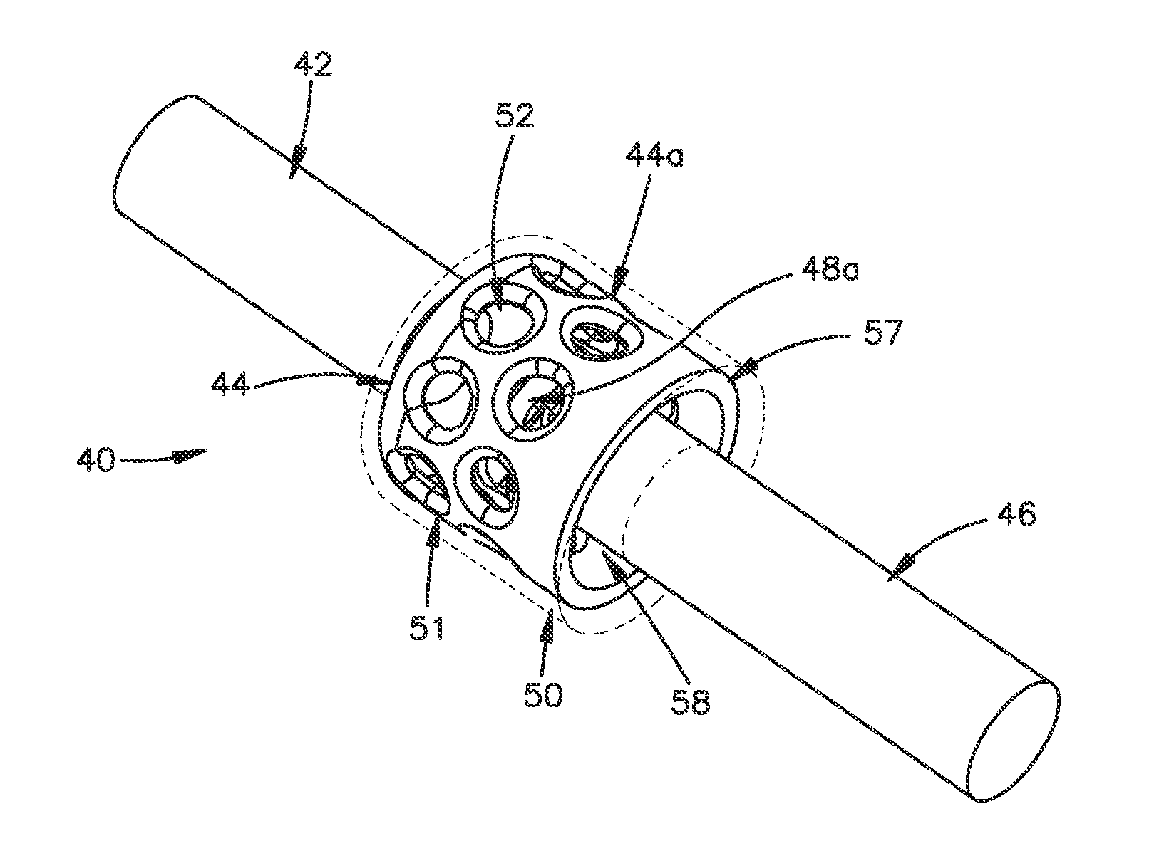
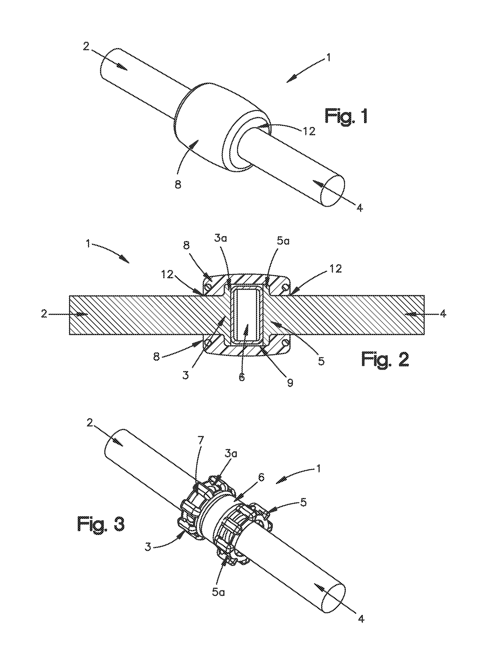
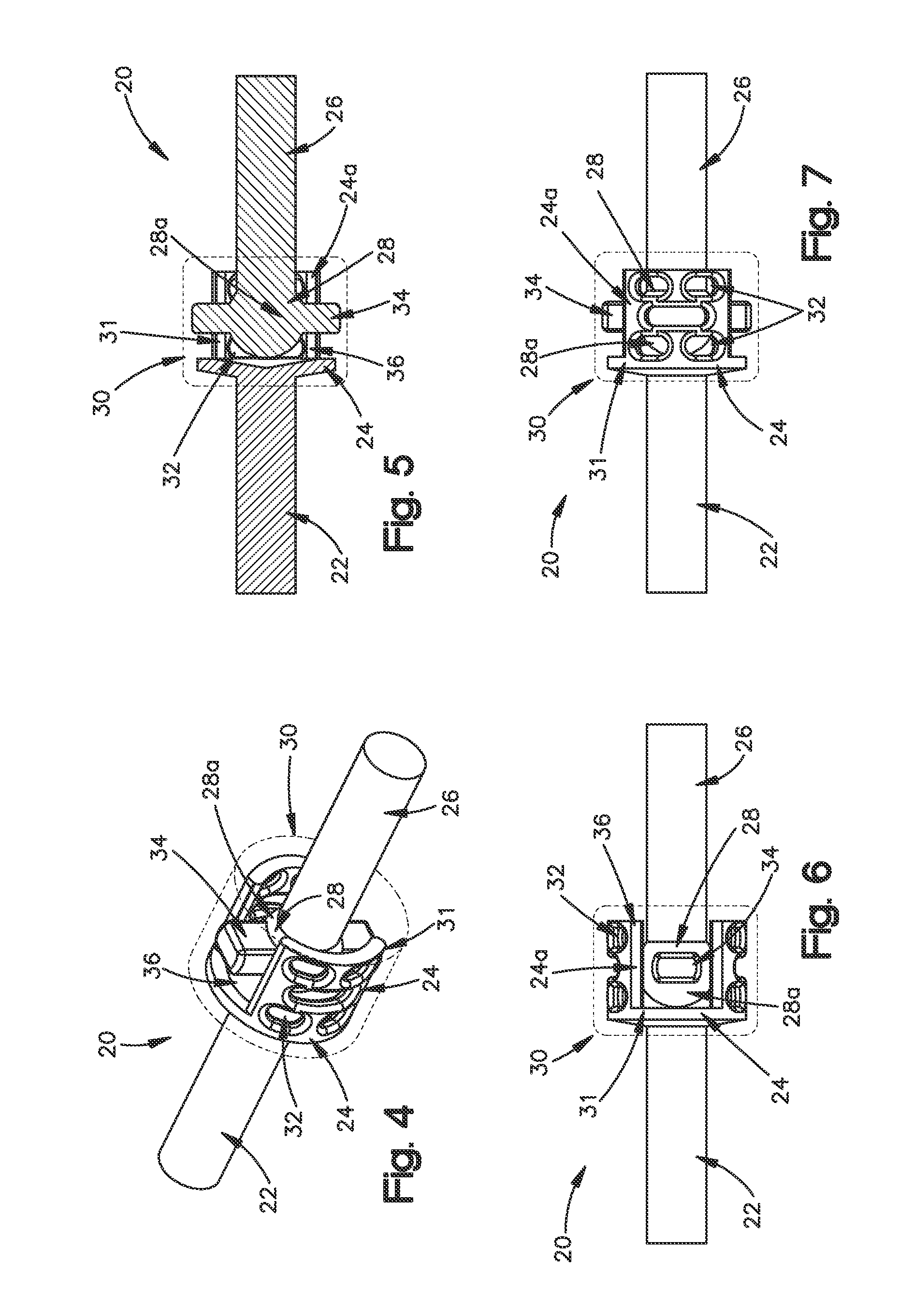
[0071]Certain exemplary embodiments of the invention will now be described with reference to the drawings. In general, such embodiments relate to a fixation system, by way of non-limiting example, a dynamic fixation system for use in posterior spinal fixation. The invention may have other applications and uses and should not be limited to the structure or use described and illustrated. As will be described in greater detail below, the dynamic fixation system may include a first rod, a second rod, and a damping mechanism and / or damping component positioned between and / or connecting the first and second rods. The damping mechanism and / or damping component permits the first rod to move (e.g., translate, angulate, rotate (e.g. twist), etc.) with respect to the second rod.

[0072]The dynamic fixation system including but not limited to the first and second rods, the optional housing, cage, end portions, tabs, locking caps, spring elements, sleeves, damping mechanism, damper, etc., may be m...


PUM


Abstract

The present invention is directed to a dynamic fixation system for engaging, via bone fixation elements, one or more parts of a patient's body. Preferably, the dynamic fixation system is used to engage one or more vertebrae for stabilizing the attached vertebrae with respect to one another while still permitting the vertebrae to move with respect to one another. The dynamic fixation system may include a first rod having first and second ends, a second rod having first and second ends, and a damping component and/or a damping mechanism for interconnecting the first and second rods. In one embodiment, the damping component is injection molded in-between the one of the ends of the first rod and one of the ends of the second rod so that the first and second rods are prevented from separating with respect to one another but are still permitted to move with respect to one another.

Description

FIELD OF THE INVENTION[0001]The invention relates to a fixation system, more specifically a dynamic spinal fixation system.BACKGROUND OF THE INVENTION[0002]Spinal fusion is a procedure that involves joining two or more adjacent vertebrae with a bone fixation device to restrict movement of the vertebra with respect to one another. For a number of known reasons, spinal fixation devices are used in spine surgery to align and / or fix a desired relationship between adjacent vertebral bodies. Such devices typically include a spinal fixation element, such as a relatively rigid fixation rod, that is coupled to adjacent vertebrae by attaching the fixation element to various bone fixation elements, such as hooks, bolts, wires, screws, etc. The fixation elements can have a predetermined contour, and once installed, the fixation element holds the vertebrae in a desired spatial relationship, either until desired healing or spinal fusion has taken place, or for some longer period of time.[0003]Rec...

Claims


Application Information

Patent Timeline
IPC IPC(8): A61B17/70
CPCA61B17/7004A61B17/7025A61B17/7023
Inventor LECHMANN, BEAT
Owner DEPUY SYNTHES PROD INC
Why Eureka
Try Eureka