Liquid ejecting head manufacturing method

Active Publication Date: 2010-03-25
SEIKO EPSON CORP
View PDF14 Cites 13 Cited by
  • Summary
  • Abstract
  • Description
  • Claims
  • Application Information

AI Technical Summary

Benefits of technology

[0011]An advantage of some aspects of the invention is that it provides a liquid ejecting head manufacturing method capable of satisfactoril

Problems solved by technology

In such an ink jet printing head, when bubbles existing inside the ink of the ink cartridge or bubbles mixed in the ink during an ink cartridge attaching or detaching operation are supplied to the head body, a problem arises in that an ejecting error such as a dot omission is caused by the bubbles.
For this reason, a gap between the adjacent ink supply needles cannot be formed to be short, which causes such a problem that the liquid ejecting head increases in size.
As a result, a problem arises in that a dr

Method used


Image

  • Liquid ejecting head manufacturing method
  • Liquid ejecting head manufacturing method
  • Liquid ejecting head manufacturing method

Examples


Example

First Embodiment

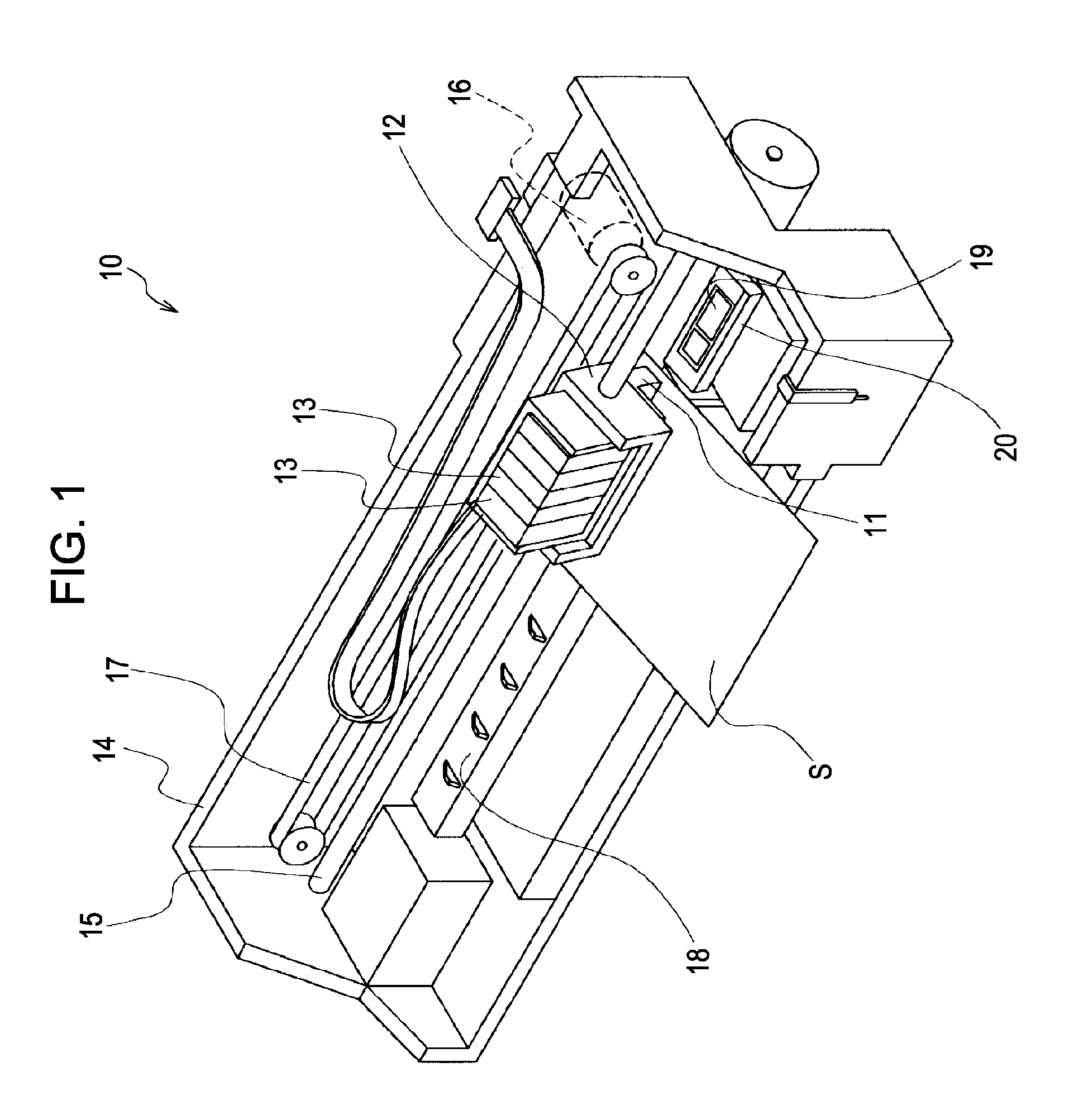
[0049]FIG. 1 is a schematic perspective view showing an ink jet printing apparatus which is an example of a liquid ejecting apparatus mounted with a liquid ejecting head obtained by a liquid ejecting head manufacturing method according to the first embodiment of the invention. As shown in FIG. 1, in an ink jet printing apparatus 10, an ink jet printing head (hereinafter, referred to as a printing head) 11 which is an example of a liquid ejecting head for ejecting ink droplets is fixed to a carriage 12, and ink cartridges 13 which are liquid storing members separably fixed to the printing head 11, where the liquid storing members store therein plural different colors such as black (B), light black (LB), cyan (C), magenta (M), and yellow (Y).

[0050]The carriage 12 mounted with the printing head 11 is formed in a carriage shaft 15 mounted on an apparatus body 14 so as to be movable in the axial direction. In addition, when driving force of a driving motor 16 is transmitt...

Example

Second Embodiment

[0085]As described above, the liquid ejecting head formed by the liquid ejecting head manufacturing method according to the first embodiment of the invention is described, but the structure of the fixed portion 34 is not limited to the examples shown in FIGS. 2 to 4. The second embodiment in which the structure of the fixed portion is different will be described with reference to FIGS. 11 to 15. In addition, the same reference numerals will be given to the same constituents as those of the above-described embodiment, and the repetitive description thereof will be omitted.

[0086]FIG. 11 is a plan view showing the supply member, and FIG. 12 is an enlarged sectional view taken along the line XII-XII in FIG. 11.

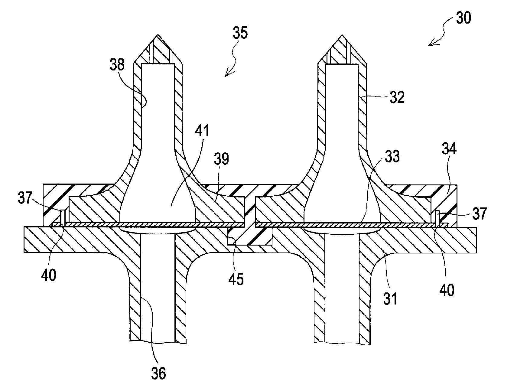
[0087]As shown in FIGS. 11 and 12, a fixed portion 44 according to this embodiment surrounds the peripheries of the supply needles 32 so as to have the portion from the supply member body 31 to the supply needles 32 in the outer peripheries of the supply needles 3...

Example

Third Embodiment

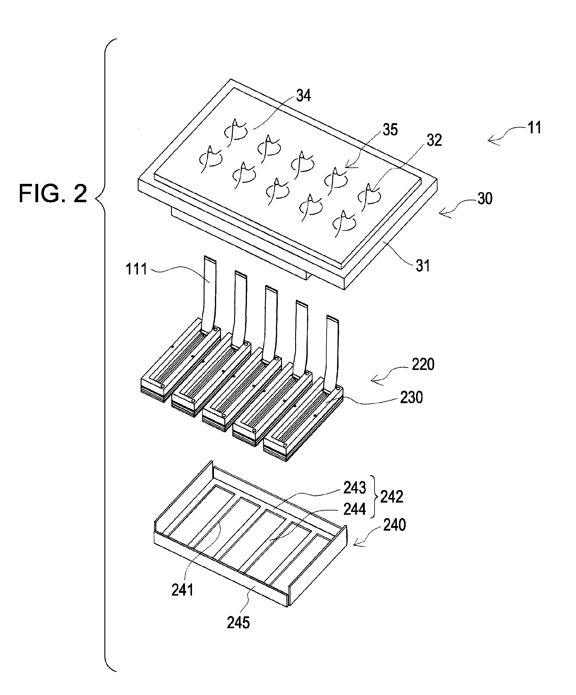
[0095]In this embodiment, the structure of the supply member is different from those of the first and second embodiments. That is, only the structure of the supply member of the printing head shown in FIG. 2 is different, and the other structures are the same as those of the first and second embodiments. Thus, the same reference numerals will be given to the same constituents as those shown in FIGS. 1 and 2, and the supply member 30A will be described in detail with reference to FIGS. 16 and 17. Here, FIG. 16 is a plan view showing the supply member, and FIG. 17 is an enlarged sectional view taken along the line XVII-XVII in FIG. 16.

[0096]As shown in FIGS. 16 and 17, a supply member 30A includes a supply member body 31A which is a first supply member; supply needles 32A which are second supply members formed on one surface of the supply member body 31A; a filter 33A which is formed between the supply member body 31A and each supply needle 32A; and a fixed portion 34A...


PUM

PropertyMeasurementUnit
Flow rateaaaaaaaaaa
Melting pointaaaaaaaaaa

Abstract

A method of manufacturing a liquid ejecting head that ejects a liquid supplied from a liquid storing member through a liquid supply path. The method includes positioning a filter to a first or second supply member by using positioning pins upon disposing the filter between first and second liquid supply paths. The first supply member has the first liquid supply path. The second supply member has the second liquid supply path on the side of one surface of the first supply member to communicate with the first liquid supply path. At least the first supply member and the second supply member are integrated such that a fixed portion is molded by injecting a resin material from an injection portion of a mold at a position where the first and second liquid supply paths are interposed between the positioning pins.

Description

BACKGROUND[0001]1. Technical Field[0002]The present invention relates to a liquid ejecting head manufacturing method, which is particularly suitable for manufacturing an ink jet printing head mounted on an ink jet printing apparatus.[0003]2. Related Art[0004]In an ink jet printing head which is a representative example of a liquid ejecting head, generally, ink is supplied from an ink cartridge as a liquid storing member having ink filled therein to a head body through an ink supply needle as an ink supply body separably inserted into the ink cartridge and an ink passageway formed in a supply member such as a cartridge casing holding the ink cartridge, and the ink supplied to the head body is ejected from a nozzle by driving a pressure generating member such as a piezoelectric element formed in the head body.[0005]In such an ink jet printing head, when bubbles existing inside the ink of the ink cartridge or bubbles mixed in the ink during an ink cartridge attaching or detaching opera...

Claims


Application Information

Patent Timeline
IPC IPC(8): B21D53/76
CPCB41J2/161Y10T29/49401B41J2/17563B41J2/1637
Inventor KOBAYASHI, HIROYUKIOWAKI, HIROSHIGE
Owner SEIKO EPSON CORP
Why Eureka
Try Eureka