Method of Automatically Controlling a Motorized Window Treatment While Minimizing Occupant Distractions

a technology of automatic control and occupant distraction, applied in the direction of motor/generator/converter stopper, dynamo-electric converter control, door/window protection device, etc., can solve the problem of many distractions for occupants of the space, and achieve the effect of minimizing occupant distractions

Active Publication Date: 2010-03-25
LUTRON TECH CO LLC
View PDF36 Cites 101 Cited by
  • Summary
  • Abstract
  • Description
  • Claims
  • Application Information

AI Technical Summary

Benefits of technology

[0006]According to an embodiment of the present invention, a method of automatically controlling a position of a motorized window treatment to control the amount of sunlight entering a space of a building through a window located in a façade of the building allows for control of a sunlight penetration distance within the space, while minimizing occupant distractions. The position of the window treatment is controllable between an open-limit position and a closed-limit position to control the sunlight penetration distance within the space. The method comprises the steps of: (1) receiving a desired maximum sunlight penetration distance for the space; (2) building a timeclock schedule having a start time and an end time, the timeclock schedule including a number of timeclock events that will occur between the start time and the end time; (3) receiving a minimum time period that may occur between any two consecutive timeclock events; (4) determining, for each of the timeclock events, an event time between the start time and the end time, such that at least the minimum time period exists between the event times of any two consecutive timeclock events; (5) determining a respective event position for each of the timeclock events to which the motorized window treatment will be controlled at the respective event time, such that the sunlight penetration distance does not exceed the desired maximum sunlight penetration distance for all of the events between the start time and the end time of the timeclock schedule; and (6) automatically controlling the motorized window treatment according to the timeclock schedule by adjusting the position of the motorized window treatment to the respective position of each of the timeclock events at the respective event time.
[0007]According to another embodiment of the present invention, the method may additionally comprise the steps of receiving a maximum number of movements that may occur during the timeclock schedule, and determining, for each of the timeclock events, an event time between the start time and the end time, such that the number of timeclock events of the timeclock schedule does not exceed the maximum number of movements, and at least the minimum time period exists between the event times of any two consecutive timeclock events.
[0008]According to another embodiment of the present invention, a method of automatically controlling a position of a motorized window treatment while minimizing occupant distractions comprises the steps of: (1) receiving a desired maximum sunlight penetration distance for the space; (2) receiving a minimum time period that may occur between any two consecutive window treatment movements; (3) calculating a controlled position to which the motorized window treatment should be controlled during each of a plurality of consecutive time intervals, such that the sunlight penetration distance does not exceed the desired maximum sunlight penetration distance during each of the respective time intervals, the time intervals having lengths greater than or equal to the minimum time period that may occur between any two consecutive window treatment movements; and (4) automatically adjusting the position of the motorized window treatment to the calculated position at the beginning of each time interval, such that the sunlight penetration distance does not exceed the desired maximum sunlight penetration distance during each of the respective time intervals, and the movements of the shades are spaced apart by at least the minimum time period that may occur between any two consecutive window treatment movements.
[0009]In addition, a load control system comprising a motorized window treatment adapted to control the amount of sunlight entering a space of a building through a window located in a façade of the building is also described herein. The position of the window treatment is controllable between an open-limit position and a closed-limit position to control a sunlight penetration distance within the space. The load control system comprises a central controller operatively coupled to the motorized window treatment and operable to transmit digital commands to the motorized window treatment. The controller receives a desired maximum sunlight penetration distance and a minimum time period that may occur between any two consecutive window treatment movements, and calculates a controlled position to which the motorized window treatment should be controlled during each of a plurality of consecutive time intervals, such that the sunlight penetration distance does not exceed the desired maximum sunlight penetration distance during each of the respective time intervals. The time intervals have lengths greater than or equal to the minimum time period that may occur between any two consecutive window treatment movements. The controller automatically adjusts the position of the motorized window treatment to the calculated position at the beginning of each time interval, such that the sunlight penetration distance does not exceed the desired maximum sunlight penetration distance during each of the respective time intervals, and the movements of the shades are spaced apart by at least the minimum time period that may occur between any two consecutive window treatment movements.
[0010]According to another aspect of the present invention, a method of automatically controlling a position of a motorized window treatment minimizes occupant distractions by only adjusting the position of the motorized window treatment twice in a 24-hour period. The motorized window treatment is adapted to control the amount of sunlight entering a space of a building through a window located in a façade of the building. The position of the window treatment is controllable between a fully-open position and a fully-closed position to control a sunlight penetration distance within the space. The method comprising the steps of: (1) receiving a desired maximum sunlight penetration distance; (2) determining a first time at which to open the motorized window treatment during the 24-hour period and a second time at which to close the motorized window treatment during the 24-hour period, such the sunlight penetration distance does not exceed the desired maximum sunlight penetration distance; (3) automatically opening the window treatment at the first time; and (4) automatically closing the window treatment at the second time.

Problems solved by technology

However, the automatic control algorithms of prior art motorized window treatments have resulted in frequent movement of the motorized window treatments, thus causing many distractions to occupants of the space.

Method used


Image

  • Method of Automatically Controlling a Motorized Window Treatment While Minimizing Occupant Distractions
  • Method of Automatically Controlling a Motorized Window Treatment While Minimizing Occupant Distractions
  • Method of Automatically Controlling a Motorized Window Treatment While Minimizing Occupant Distractions

Examples


first embodiment

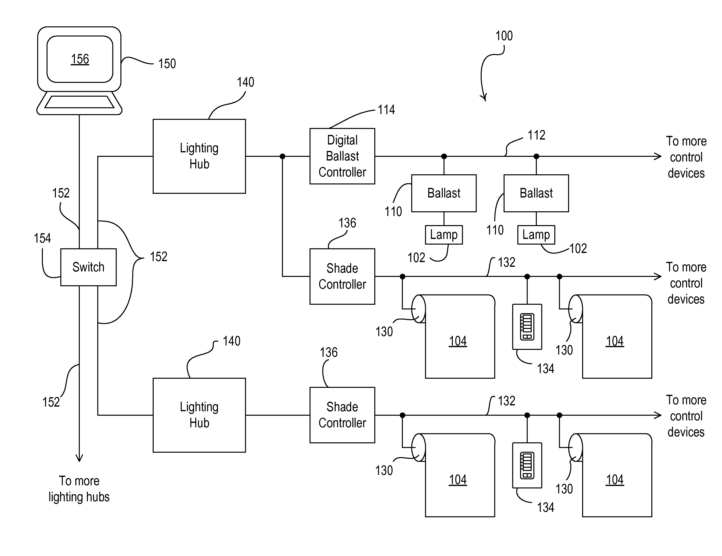
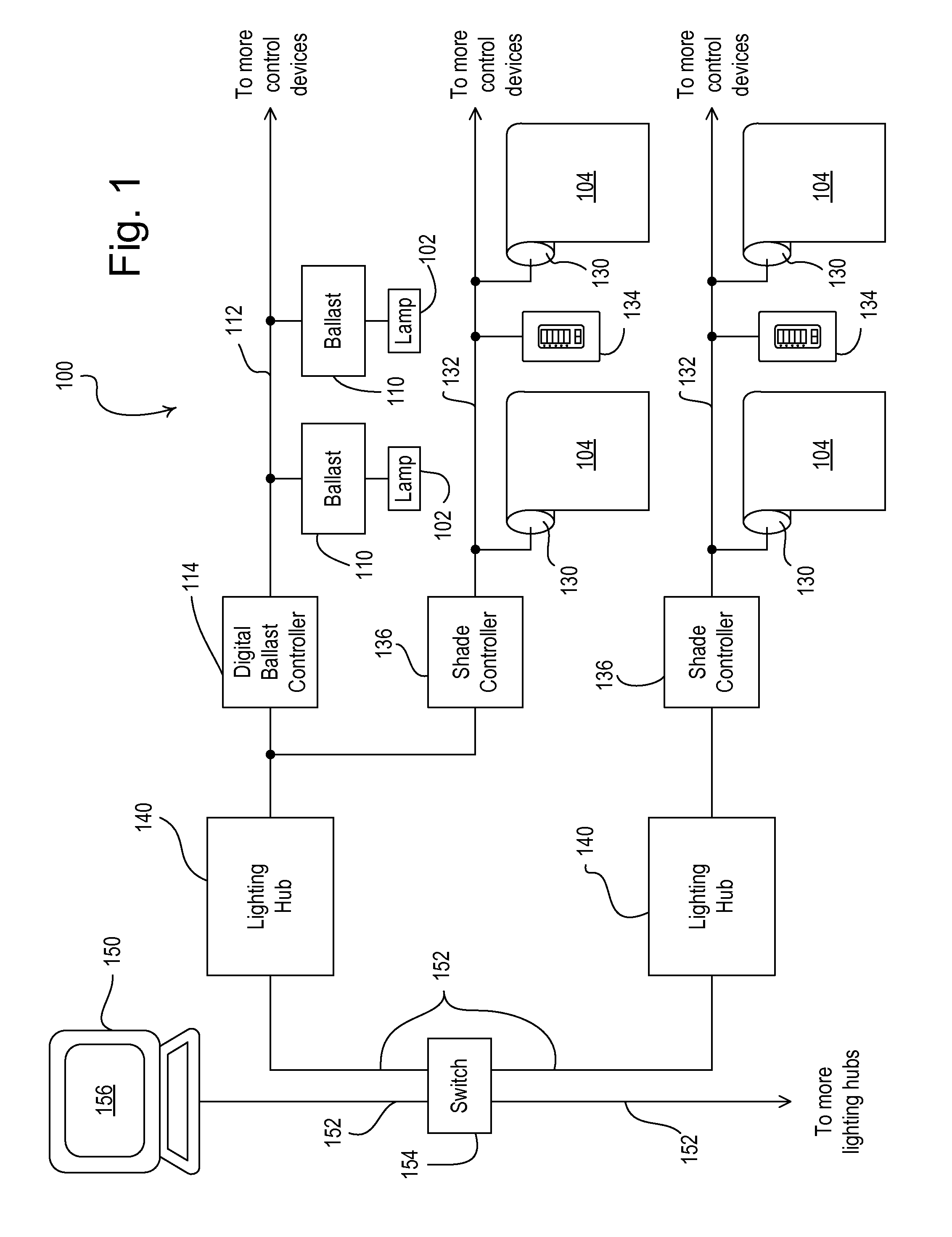
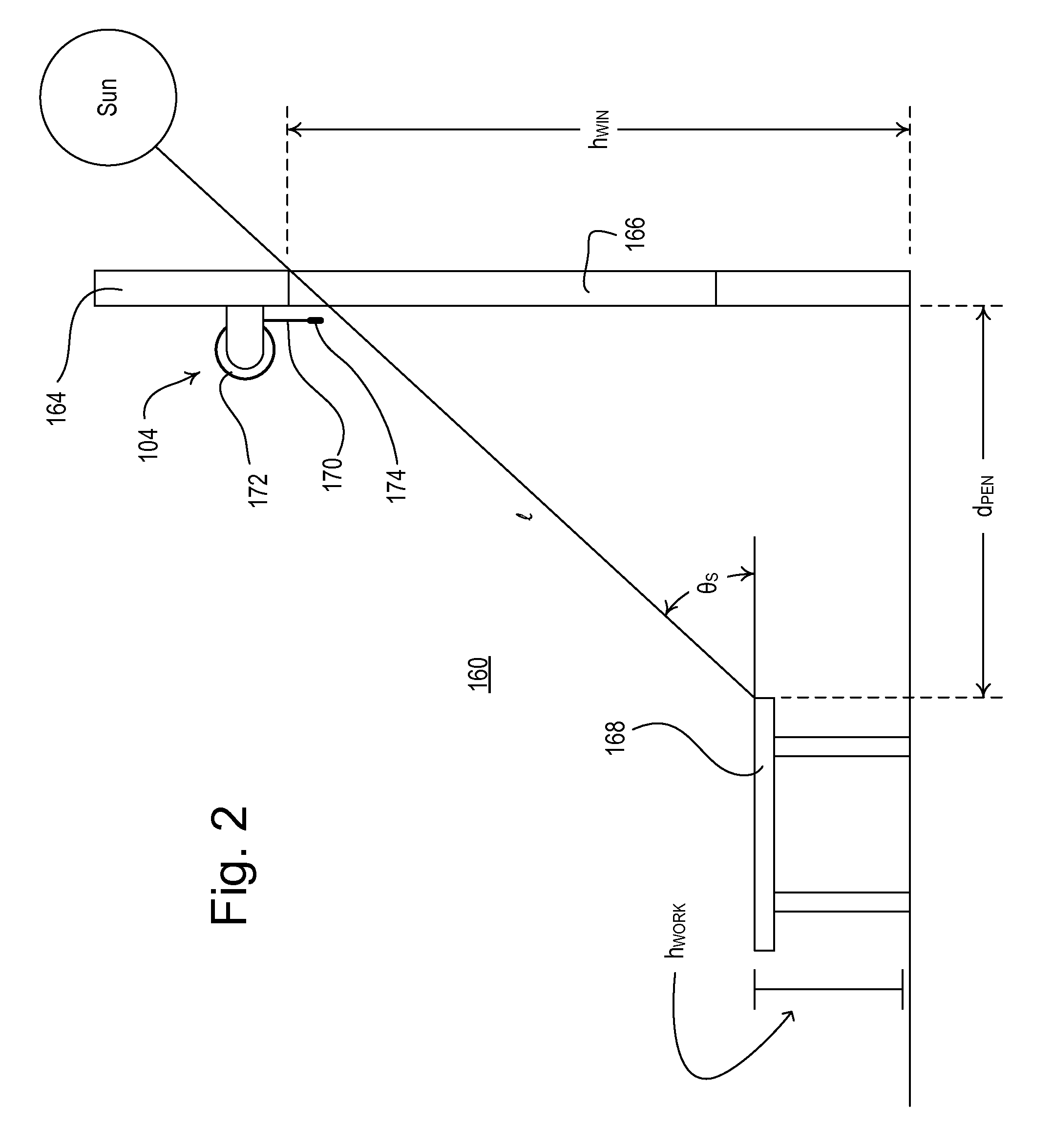
[0048]According to the present invention, the motorized roller shades 104 are controlled such that the sunlight penetration distance dPEN is limited to less than a desired maximum sunlight penetration distance dMAX during all times of the day. For example, the sunlight penetration distance dPEN may be limited such that the sunlight does not shine directly on the table 168 to prevent sun glare on the table. The desired maximum sunlight penetration distance dMAX may be entered using the GUI software of the PC 150 and may be stored in memory in each of the lighting hubs 140. In addition, the user may also use the GUI software of the PC 150 to enter and the present date and time, the present timezone, the local longitude λ and latitude Φ of the building 162, the façade angle φF for each façade 164 of the building, the height hWIN of the windows 166 in spaces 160 of the building, and the heights hWORK of the workspaces (i.e., tables 168) in the spaces of the building. These operational c...

second embodiment

[0056]FIG. 7 is a simplified flowchart of a timeclock configuration procedure 400 executed periodically by the lighting hub 140 of the load control system 100 to generate a timeclock schedule defining the desired operation of the motorized roller shades 104 of each of the façades 164 of the building 162 according to the present invention. For example, the timeclock configuration procedure 400 may be executed once each day at midnight to generate a new timeclock schedule for one or more areas in the building 162. The timeclock schedule is executed between a start time tSTART and an end time tEND of the present day. During the timeclock configuration procedure 400, the lighting hub 140 first performs an optimal shade position procedure 500 for determining optimal shade positions POPT(t) of the motorized roller shades 104 in response to the desired maximum sunlight penetration distance dMAXfor each minute between the start time tSTART and the end time tEND of the present day. The light...

third embodiment

[0081]According to the present invention, the lighting hub 140 generates a timeclock schedule in response to a maximum number NMAX of movements of the motorized roller shades 104 that may occur during the present day, as well as in response to the minimum time period TMIN that may exist between any two consecutive movements of the motorized roller shades. As in the first two embodiments of the present invention, the timeclock schedule provides for control of the motorized roller shades 104 to limit the sunlight penetration distance dPEN to be less than the desired maximum sunlight penetration distance dMAX. The desired maximum sunlight penetration distance dMAX, the maximum number NMAX of roller shade movements, and the minimum time period TMIN between shade movements may be stored in the memory in the lighting hub 140 and may be entered by a user using the GUI software of the PC. For example, the maximum number NMAX of roller shade movements may have a minimum value of approximatel...


PUM


Abstract

A load control system provides for automatically controlling a position of a motorized window treatment to control the amount of sunlight entering a space of a building through a window located in a façade of the building in order to control a sunlight penetration distance within the space and minimize occupant distractions. The load control system automatically generates a timeclock schedule having a number of timeclock events for controlling the position of the motorized window treatment during the present day. A user is able to select a desired maximum sunlight penetration distance for the space and a minimum time period that may occur between any two consecutive timeclock events. In addition, a maximum number of movements that may occur during the timeclock schedule may also be entered. The load control system uses these inputs to determine event times and corresponding positions of the motorized window treatment for each timeclock event of the timeclock schedule.

Description

CROSS REFERENCE TO RELATED APPLICATIONS[0001]This application claims priority from commonly-assigned U.S. Provisional Patent Application No. 61 / 100,162, filed Sep. 25, 2008, and U.S. Provisional Patent Application No. 61 / 232,948, filed Aug. 11, 2009, both entitled METHOD OF AUTOMATICALLY CONTROLLING A MOTORIZED WINDOW TREATMENT WHILE MINIMIZING OCCUPANT DISTRACTIONS. The entire disclosures of both applications are hereby incorporated by reference.BACKGROUND OF THE INVENTION[0002]1. Field of the Invention[0003]The present invention relates to a load control system for controlling a plurality of electrical loads and a plurality of motorized window treatments in a space, and more particularly, to a procedure for automatically controlling one or more motorized window treatments to prevent direct sun glare on work spaces in the space while minimizing occupant distractions.[0004]2. Description of the Related Art[0005]Motorized window treatments, such as, for example, motorized roller shad...

Claims


Application Information

Patent Timeline
Patent Type & Authority Applications(United States)
IPC IPC(8): E05F15/20H02P1/00E06B9/24
CPCE05F17/00E05Y2400/40E05Y2400/42E05Y2800/21E05Y2900/148E05F15/71E06B9/68E06B2009/6818H02P1/18E05F15/20E05F15/70E06B9/322E05Y2900/106E05Y2900/00
Inventor ZAHARCHUK, WALTER S.COURTNEY, BRIAN MICHAELFRICKE, WILLIAM BRYCEHOWE, WILLIAM H.MAJEWSKI, TIMOTHY S.SPIRA, JOEL S.
Owner LUTRON TECH CO LLC
Why Eureka
Try Eureka