Evaporator for looped heat pipe system

a looped heat pipe and looped technology, applied in the direction of indirect heat exchangers, lighting and heating apparatus, etc., can solve the problems of limiting the formation of inner structures in the desired shape, heat transfer to the sintered wicks is not smooth, and the electrical components of the central processing unit or semiconductor chips used in various electronic devices such as computers generate a large amount of heat during operation, so as to improve the contact state

Inactive Publication Date: 2010-03-25
ZALMAN TECH CO LTD +1
View PDF62 Cites 21 Cited by
  • Summary
  • Abstract
  • Description
  • Claims
  • Application Information

AI Technical Summary

Benefits of technology

[0023]The present invention provides an evaporator for a looped heat pipe (LHP) system, wherein heat transferring fins of the evaporator can be formed in various shapes, and wicks of the evaporator can be formed in various shapes and of various materials, thereby improving a contact state between the heat transferring fins and the wicks.

Problems solved by technology

Electronic parts such as central processing units (CPUs) or semiconductor chips used for various electronic devices such as computers generate a large amount of heat during operation.
Even though the sintered wicks and the base functioning as a heat plate apparently form a large cross-contact area, if a state of an actual contact interface between the sintered wicks and the base is not desirable, a heat transfer toward the sintered wicks is not smoothly performed.
However, there is a limit in forming the inner structures in the desired shapes, and in this case, a state of the contact surface is not desirable such that heat transfer is not effectively performed.
Such limits are major factors that make improvement of a contact surface state difficult.
Thus, there is a limit in obtaining the various shapes of the wicks 410.
Accordingly, the thermal contact resistance is high due to an undesirable state of a contact interface between the protrusion 120 and the wick 410, and cooling of an electronic part is not effectively performed.

Method used


Image

  • Evaporator for looped heat pipe system
  • Evaporator for looped heat pipe system
  • Evaporator for looped heat pipe system

Examples


Embodiment Construction

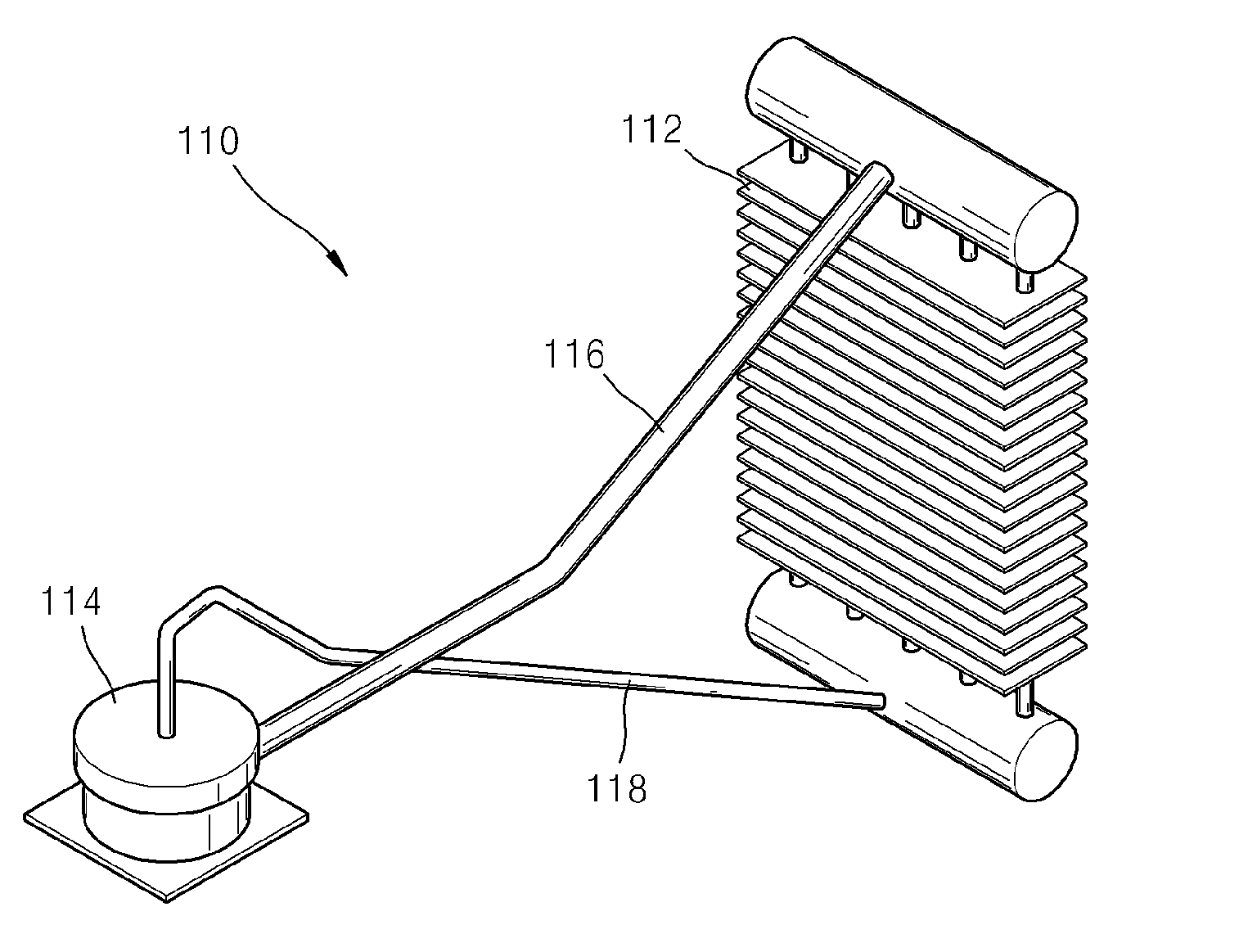
[0042]The present invention relates to an evaporator for a looped heat pipe (LHP) system including a condenser, a vapor transport line, and a liquid transport line.

[0043]Operations of the LHP system correspond to those described above in relation to the conventional technology.

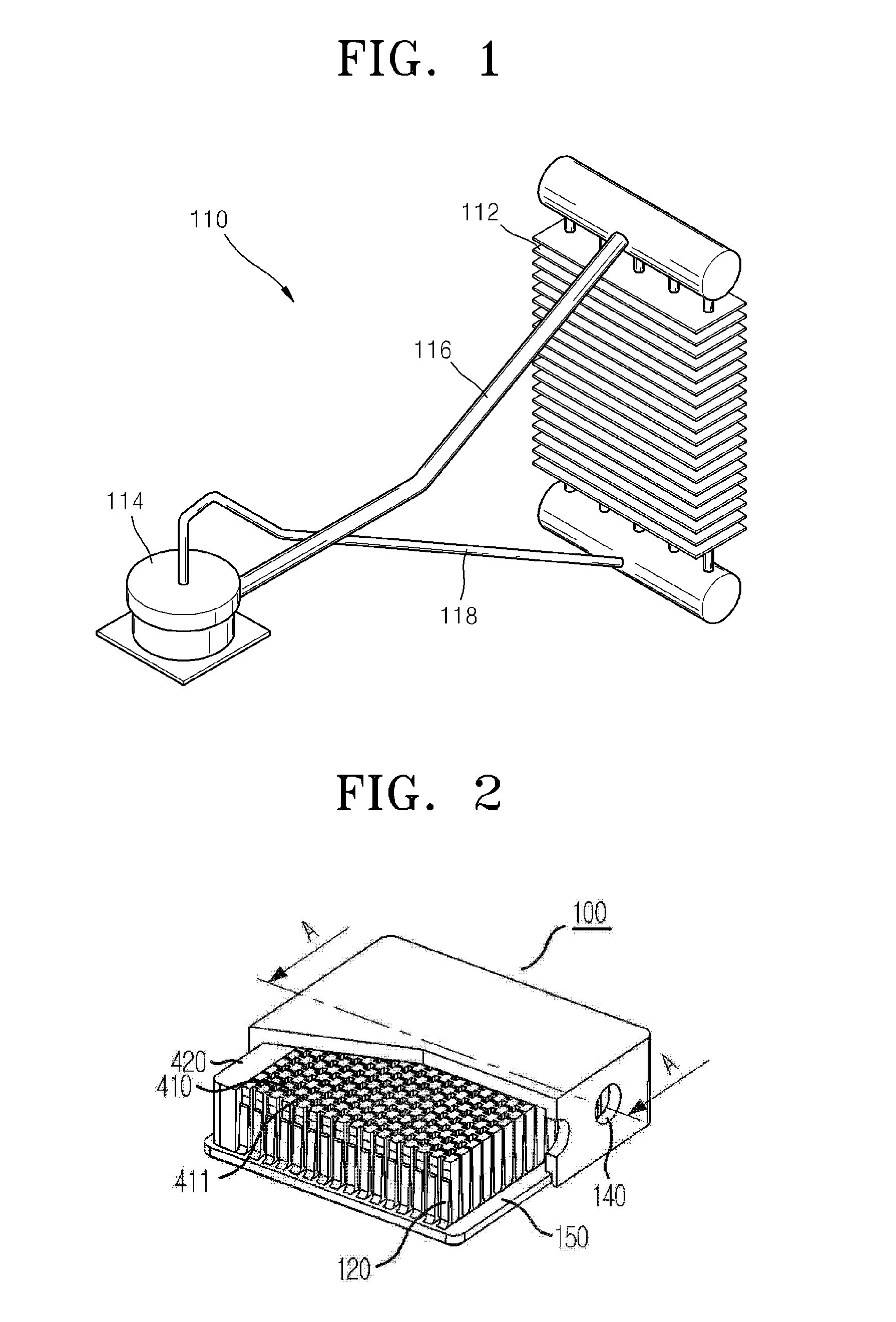
[0044]A structure of an evaporator 1 for a LHP system according to an embodiment of the present invention will be described with reference to FIGS. 6 through 10. FIG. 6 is an exploded perspective view of the evaporator 1.

[0045]The evaporator 1 includes a plurality of wicks 10, a plurality of heat transferring fins 20, a unit assembly 30, an assembly structure 40, a heat transferring plate 50, and a cover member 60.

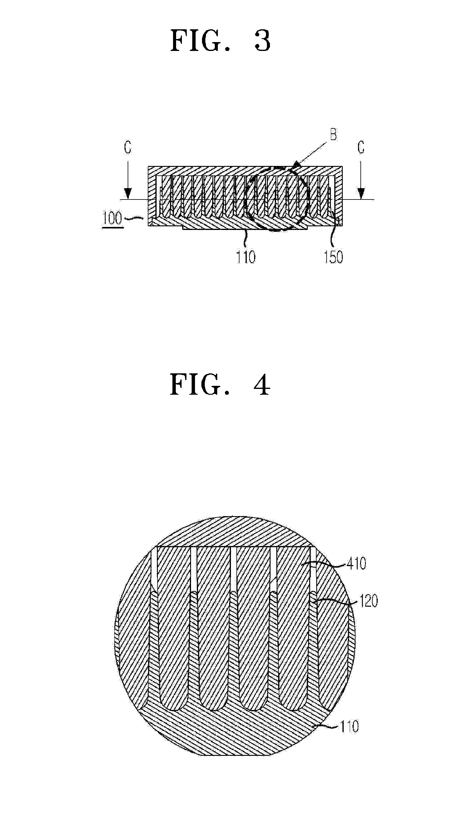
[0046]Referring to FIG. 7, each of the wicks 10 has a thin plate shape. The wicks 10 are respectively coupled to the heat transferring fins 20, and are horizontally disposed.

[0047]Each of the wicks 10 is a separate member, thus, it is easy to form the wicks 10 to have various shapes. The shape of the...


PUM


Abstract

An evaporator for a looped heat pipe (LHP) system, the evaporator including a plurality of wicks having pores formed therein; a plurality of heat transferring fins respectively having a wick coupler to be coupled to one of the plurality of wicks; a plurality of unit assemblies formed by respectively coupling each of the wicks and each of the heat transferring fins; an assembly structure formed by horizontally disposing the unit assemblies to enable a bottom surface of each of the unit assemblies to be located on a planar surface; a heat transferring plate coupled to a bottom part of the assembly structure; and a covering member coupled to the heat transferring plate.

Description

CROSS-REFERENCE TO RELATED APPLICATIONS[0001]The present application is a continuation of pending International patent application PCT / KR2008 / 005694 filed on Sep. 25, 2008, which designates the United States and claims priority from Korean patent application 10 2008 0092421 filed on Sep. 25, 2008, the content of which is incorporated herein by reference.FIELD OF THE INVENTION[0002]The present invention relates to an evaporator for a looped heat pipe (LHP) system including a condenser, a vapor transport line, and a liquid transport line, and more particularly, to an evaporator for a LHP system, wherein the evaporator has a structure in which a wick and a heat transferring fin to be coupled to the wick are separately formed and then coupled to a heat transferring plate in a wing direction, and wherein the wick and the heat transferring fin are respectively formed having various shapes and sizes so that the thermal contact resistance between the wick and the heat transferring fin can b...

Claims


Application Information

Patent Timeline
Patent Type & Authority Applications(United States)
IPC IPC(8): F28D15/04
CPCF28D15/046F28D15/0266
Inventor KIM, CHUL-JUSEO, MIN-WHANSUNG, BYUNG-HOYOO, JUNG-HYUNCHOI, JEE-HOONJO, JUNG RAE
Owner ZALMAN TECH CO LTD
Why Eureka
Try Eureka