Compartment divider assembly

a technology of compartment dividers and assembly parts, which is applied in the direction of show shelves, show hangers, show stands, etc., can solve the problems of cumbersome steps required to make adjustments, and achieve the effect of improving the efficiency of the adjustment process

Inactive Publication Date: 2010-03-25
ARTICULATION
View PDF33 Cites 34 Cited by
  • Summary
  • Abstract
  • Description
  • Claims
  • Application Information

AI Technical Summary

Benefits of technology

The present invention is a compartment divider assembly that allows users to create separate spaces within a compartment and easily adjust the size of those spaces to accommodate items of different shapes and sizes. The assembly includes a first divider, second divider, and interior frame that can be moved to create the divided spaces. The technical effect of this invention is that it provides a flexible and customizable solution for creating separate spaces within a compartment, making it easier to organize and protect items.

Problems solved by technology

The technical problem addressed in this patent text is the need for efficient and secure ways to organize various items in limited spaces, while protecting them from damage and unsecured items. Existing devices for securing, bracing, or separating objects are typically designed for a specific type of item, space, or compartment, and can be cumbersome to adjust. The patent aims to provide a solution that can accommodate a variety of items and offers easy adjustments.

Method used


Image

  • Compartment divider assembly
  • Compartment divider assembly
  • Compartment divider assembly

Examples


Embodiment Construction

of Compartment Divider Assembly and Components

[0039]A Two-Divider Assembly with Each Divider Including a Single Rail (No Exterior Frame)

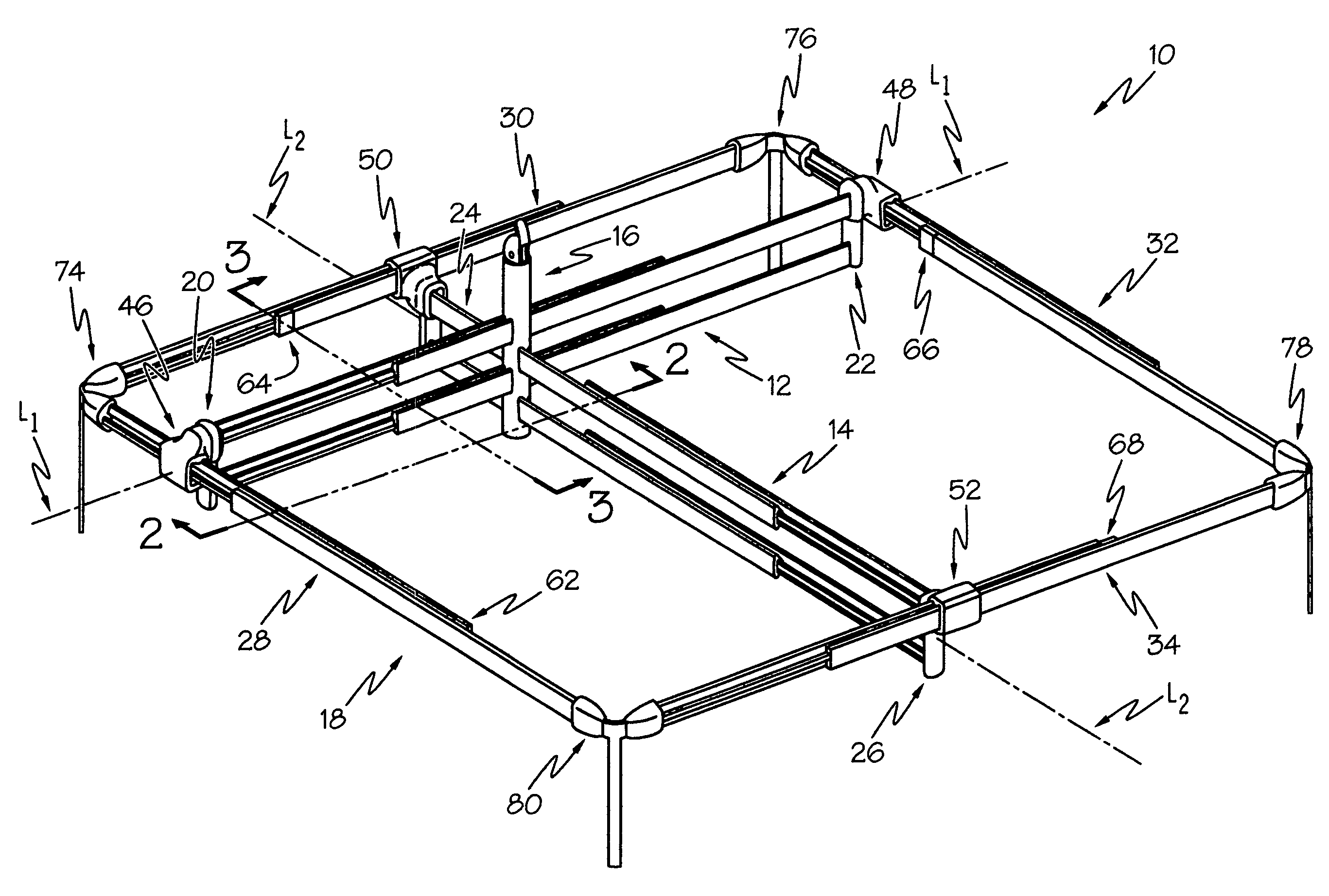
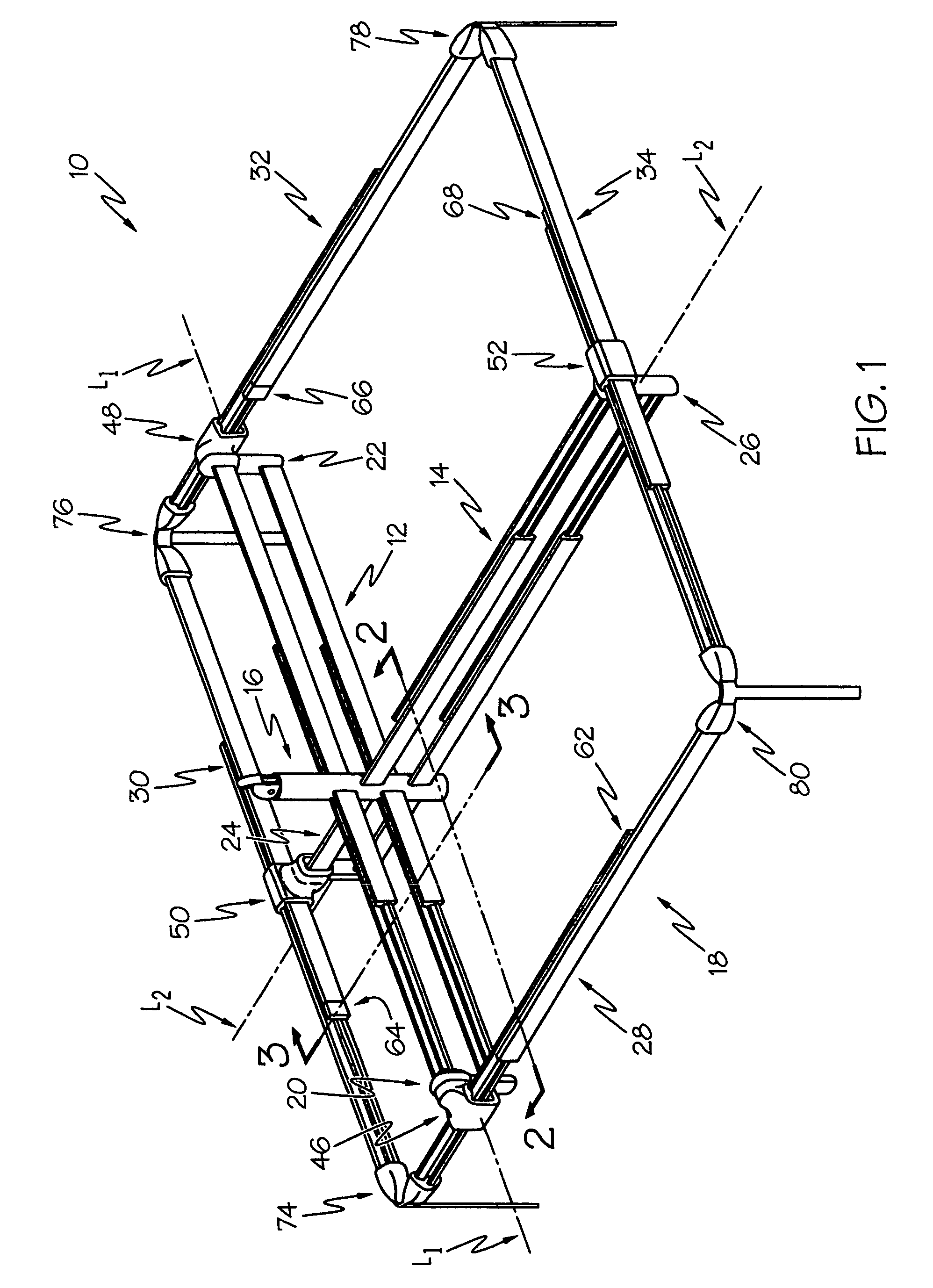
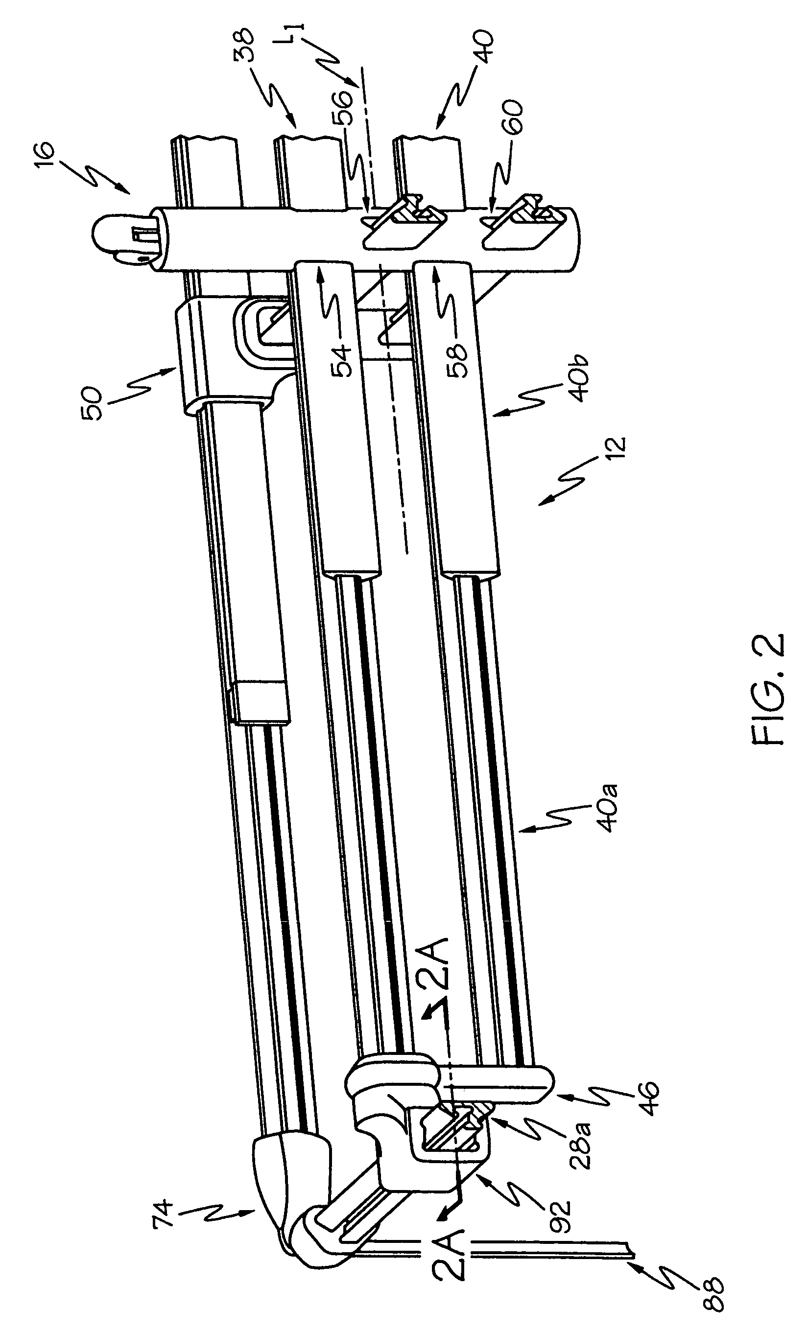
[0040]Each of the first and second dividers includes a single rail, as opposed to, e.g., multiple parallel rails. The dividers are perpendicular to each other, and the rails are moveable back and forth through the interior frame. The interior frame includes a releasable lock assembly.

A Two-Divider Assembly with Each Divider Including a Pair of Parallel Spaced-Apart Rails (No Exterior Frame)

[0041]Each of the first and second dividers includes two parallel spaced-apart rails. The dividers are perpendicular to each other, and the rails are moveable back and forth through the interior frame. The interior frame includes, in sequential order, first, second, third, and fourth passageways. The first divider rails are moveable back and forth through the first and third passageways respectively; and the second divider rails are moveable back and forth through...


PUM


Abstract

A compartment divider assembly, in accordance with the principles of the invention, may include a first divider having a longitudinal axis, a second divider having a longitudinal axis that crosses the longitudinal axis of the first divider, and an interior frame—with each of the first and second dividers being moveable back and forth through the interior frame. If desired, the assembly may further include an exterior frame, with at least one end of at least one of the first and second dividers connected to the exterior frame.

Description


Claims


Application Information

Patent Timeline
Owner ARTICULATION
Why Eureka
Try Eureka