Portable Photodynamic Disinfection Light Delivery Device for Catheter

a technology of photodynamic disinfection and light delivery device, which is applied in the direction of x-ray tubes with very high current, tube connectors, radiation therapy, etc., can solve the problems of creating a serious infection risk, and achieve the effects of reducing the incidence of hai's, and being effective non-antibioti

Inactive Publication Date: 2010-03-25
ONDINE INT
View PDF5 Cites 35 Cited by
  • Summary
  • Abstract
  • Description
  • Claims
  • Application Information

AI Technical Summary

Benefits of technology

[0008]Photodynamic disinfection is the use of a photosensitizer activated by light or electromagnetic radiation of specific wavelength(s) to inhibit or eliminate microbes including pathogens. Photodynamic disinfection has been demonstrated to be an effective non-antibiotic antimicrobial approach in vitro. One major advantage of photodynamic disinfection is that it is not subject to issues of resistance that plague the use of antibiotics. Another advantage of photodynamic disinfection is the photosensitizer(s) used for photodynamic disinfection are biocompatible and environmentally friendly with minimal, if any, side effects; especially when they are used in low concentrations. Photodynamic disinfection can also be used to disinfect inanimate surfaces and medical devices such as catheters, catheter connections, medical tubing, or the like in healthcare settings thereby reducing the incidences of HAI's.
[0010]The present invention provides a catheter disinfection method comprising: applying circumferential illumination at a wavelength that activates a photosensitizer located at a catheter disinfection site so as to reduce microbes located at the catheter disinfection site using the portable photodynamic disinfection light device described above.

Problems solved by technology

Antibiotic resistant pathogens often colonize medical devices used in healthcare settings such as catheters, thereby creating a serious risk for infection.

Method used


Image

  • Portable Photodynamic Disinfection Light Delivery Device for Catheter
  • Portable Photodynamic Disinfection Light Delivery Device for Catheter
  • Portable Photodynamic Disinfection Light Delivery Device for Catheter

Examples


Embodiment Construction

[0021]A. Photodynamic Disinfection Light Delivery Device

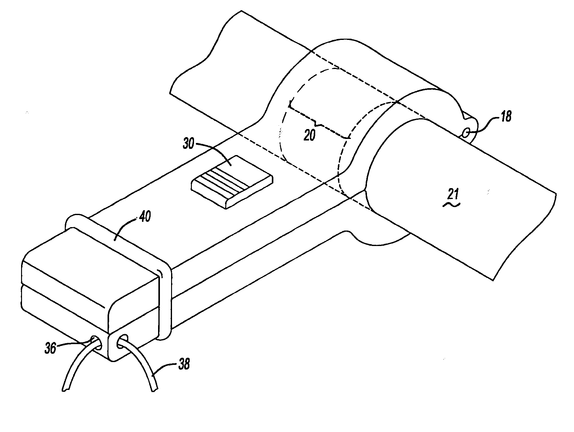
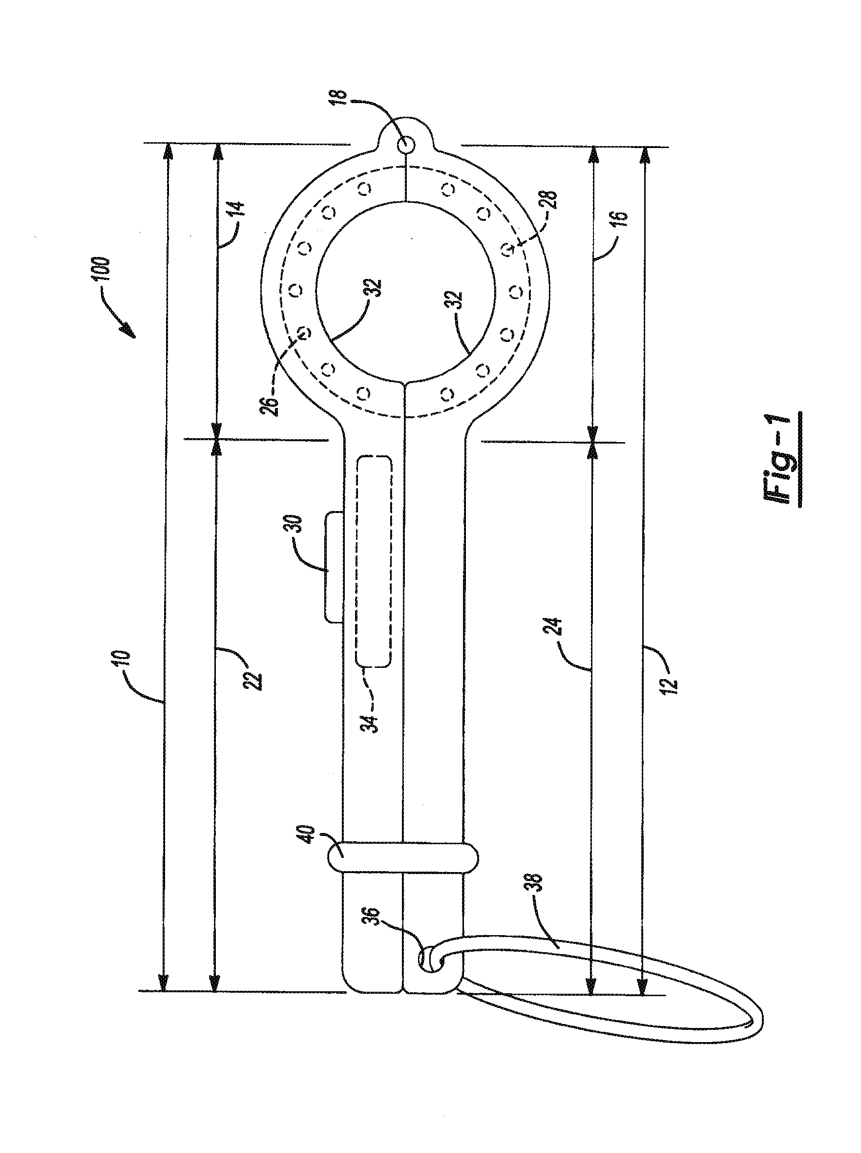
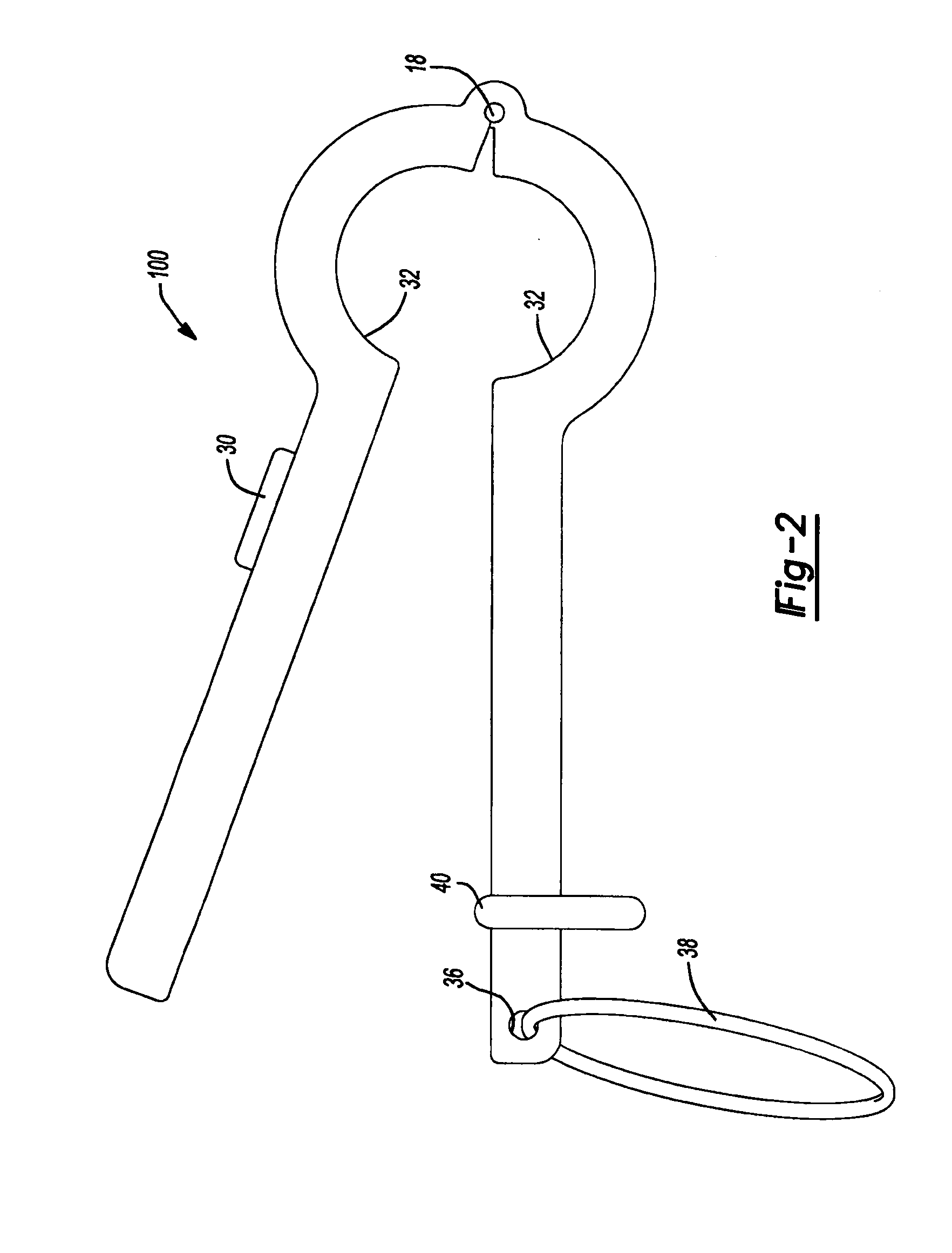
[0022]Referring to FIGS. 1-3, the present invention provides for a photodynamic disinfection light delivery device 100 comprising a housing 8 having two members 10, 12 each having a clamp portion 14, 16 that can be connected to each other with attachment means 18 to form a clamp that surrounds a catheter disinfection site 20. Each of the members 10, 12 may optionally have a handle portion 22, 24 that facilitates opening, closing, and handling of the device 100. Each clamp portion (14, 16) accepts a light source (26, 28) thereby allowing the light sources 26, 28 to be in opposing of each other (e.g., facing or opposing each other). The light sources 26, 28 provide desired wavelength(s) that activate at least one photosensitizer located at the catheter disinfection site 20 so as to reduce microbes located at the catheter disinfection site 20. “To reduce microbes” means for the purpose of this specification, to reduce, inhibit, el...


PUM

PropertyMeasurementUnit
wavelengthsaaaaaaaaaa

Abstract

The present invention provides a portable photodynamic disinfection light delivery device comprising: two opposing light sources, an energy source to supply energy to the light sources, and a housing for receiving the two light sources and the energy source; wherein (i) the housing includes two members each having a clamp portion for receiving one of the two light sources and an attachment mean connecting the clamp portions; (ii) the clamp portions during photodynamic disinfection surround a catheter disinfection site; and (iii) the two light sources together provide circumferential illumination at least one wavelength that can activate at least one photosensitizer so as to reduce microbes located at the catheter disinfection site. The present invention provides a catheter disinfection method comprising: applying circumferential illumination at a wavelength that activates a photosensitizer located at a catheter disinfection site so as to reduce microbes located at the catheter disinfection site using the portable photodynamic disinfection light device described above.

Description

CLAIM OF BENEFIT OF FILING DATE[0001]This application claims the benefit of the filing date of U.S. Provisional Application Ser. No. 61 / 099,239 titled: “PORTABLE PHOTODYNAMIC DISINFECTION LIGHT DELIVERY DEVICE FOR CATHETER DISINFECTION” filed on Sep. 23, 2008, and the filing date of PCT Application No. PCT / US09 / 57699 titled: “PORTABLE PHOTODYNAMIC DISINFECTION LIGHT DELIVERY DEVICE FOR CATHETER DISINFECTION” filed on Sep. 21, 2009, both applications incorporated herein by reference for all purposes.FIELD OF INVENTION[0002]The present invention relates to a portable photodynamic disinfection light delivery device. More specifically, it relates to a portable photodynamic disinfection light delivery device that provides circumferential illumination at desired wavelength(s) for photodynamic disinfection of catheters and related components (e.g., catheter connectors, hubs, tubing, etc.).BACKGROUND OF INVENTION[0003]Antibiotic resistant pathogens often colonize medical devices used in hea...

Claims


Application Information

Patent Timeline
Patent Type & Authority Applications(United States)
IPC IPC(8): A61L2/10A61L2/08
CPCA61L2/10A61L2202/16A61N2005/0652A61M2039/167A61N5/062A61L2202/24
Inventor STREET, CALELEDUC, PIERRELEACY, CAROLLATHAM, MARCUS ALAN
Owner ONDINE INT
Why Eureka
Try Eureka