Wide Angle Impedance Matching Using Metamaterials in a Phased Array Antenna System

a phased array, antenna technology, applied in the direction of antenna details, protective material radiating elements, antennas, etc., can solve the problems of limited improvement, achieve the effect of minimizing return loss, minimizing return loss, and minimizing return loss

Active Publication Date: 2010-03-25
THE BOEING CO
View PDF2 Cites 54 Cited by
  • Summary
  • Abstract
  • Description
  • Claims
  • Application Information

AI Technical Summary

Benefits of technology

[0004]In accordance with an embodiment of the present invention, a phased array antenna system may include a sheet of conductive material with a plurality of aperture antenna elements formed in the sheet of conductive material. Each of the plurality of aperture antenna elements is capable of sending and receiving electromagnetic energy. The phased array antenna system may also include a wide angle impedance match (WAIM) layer of material disposed over the plurality of aperture antenna elements formed in the sheet of conductive material. The WAIM layer of material includes a plurality of metamaterial particles. The plurality of metamaterial particles are selected and arranged to minimize return loss and to optimize an impedance match between the phased array antenna system and free space to permit scanning of the phased array antenna system up to a predetermined angle in elevation and all azimuthal angles.
[0005]In accordance with another embodiment of the present invention, a communications system may include a transceiver to transmit and receive electromagnetic signals and a tracking and scanning module coupled to the transceiver. A phased array antenna system may be coupled to the tracking and scanning module. The phased array antenna system may include a sheet of conductive material with a plurality of aperture antenna elements formed in the conductive sheet. Each of the

Problems solved by technology

Isotropic dielectric materials have been used for impedance matching of phased array a

Method used


Image

  • Wide Angle Impedance Matching Using Metamaterials in a Phased Array Antenna System
  • Wide Angle Impedance Matching Using Metamaterials in a Phased Array Antenna System
  • Wide Angle Impedance Matching Using Metamaterials in a Phased Array Antenna System

Examples


Embodiment Construction

[0014]The following detailed description of embodiments refers to the accompanying drawings, which illustrate specific embodiments of the invention. Other embodiments having different structures and operations do not depart from the scope of the present invention.

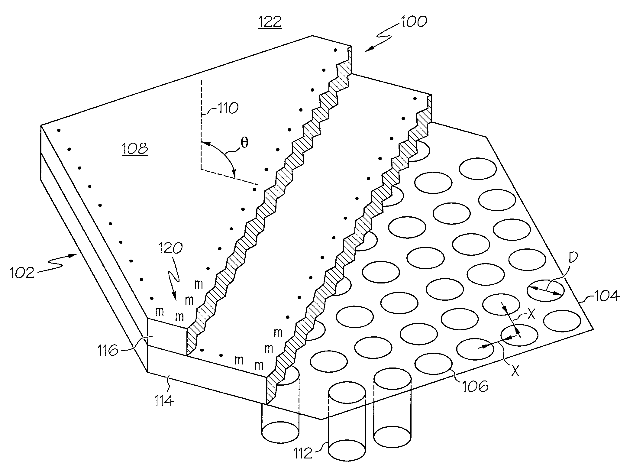
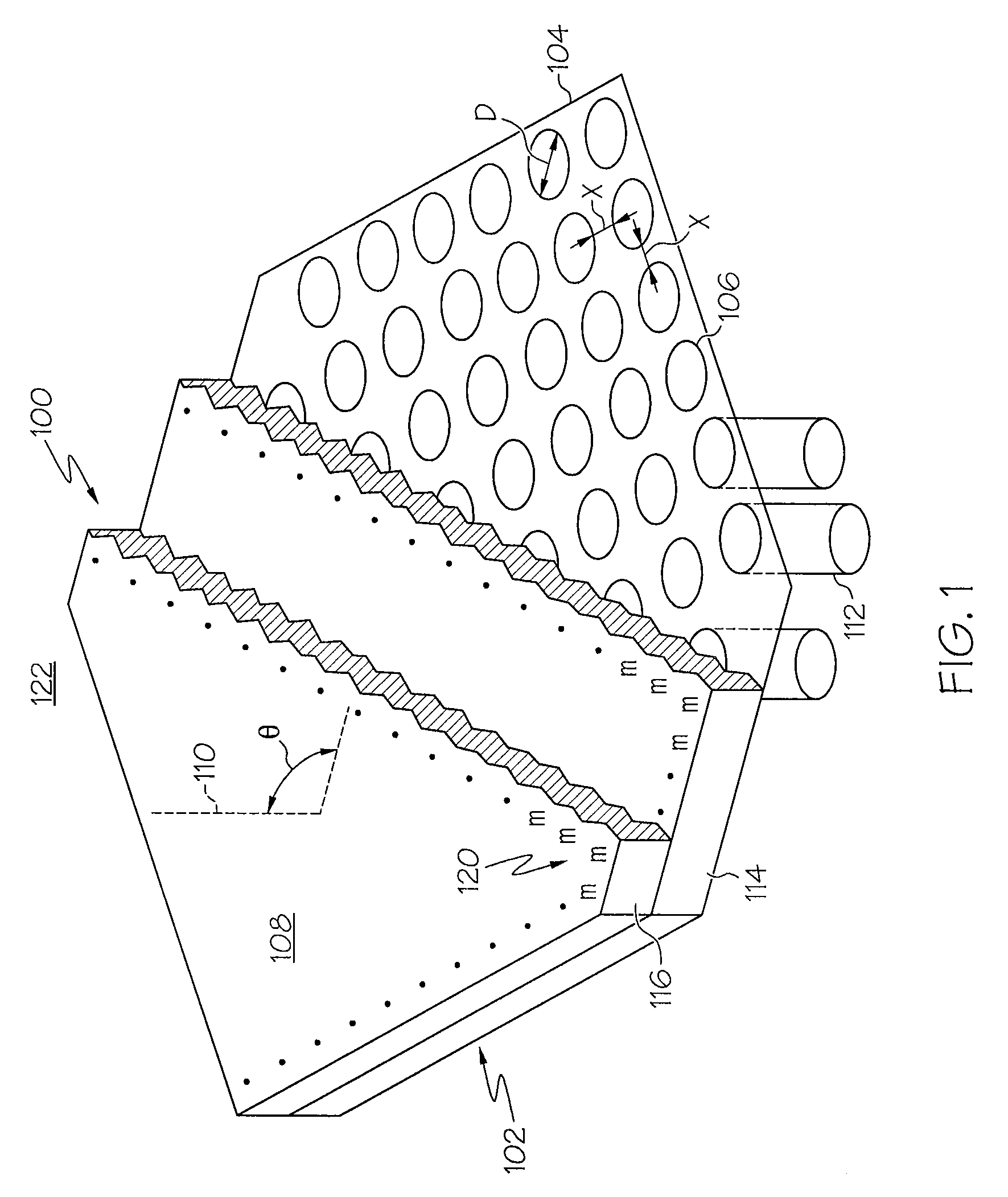
[0015]FIG. 1 is a perspective view of an example of a phased array antenna system 100 with a wide angle impedance match (WAIM) feature 102 using metamaterials in accordance with an aspect of the present invention. The phased array antenna system 100 may include a sheet of conductive material 104. A plurality of aperture antenna elements 106 or radiating apertures may be formed in the conductive sheet 104. The aperture antenna elements 106 may collectively send and / or receive electromagnetic energy and, as described herein, may be controlled to scan to a large angle θ of radiation propagation relative to a normal or perpendicular angle relative to a front face 108 of the phased array antenna system 100 as illustrated by the ...


PUM


Abstract

A phased array antenna system may include a sheet of conductive material with a plurality of aperture antenna elements formed in the sheet of conductive material. Each of the plurality of aperture antenna elements is capable of sending and receiving electromagnetic energy. The phased array antenna system may also include a wide angle impedance match (WAIM) layer of material disposed over the plurality of aperture antenna elements formed in the sheet of conductive material. The WAIM layer of material includes a plurality of metamaterial particles. The plurality of metamaterial particles are selected and arranged to minimize return loss and to optimize an impedance match between the phased array antenna system and free space to permit scanning of the phased array antenna system up to a predetermined angle in elevation.

Description

[0001]This invention was made with Government support under HR0011-05-C-0068 awarded by DARPA. The government has certain rights in this invention.FIELD[0002]The present invention relates to antennas, antenna arrays and the like, and more particularly to wide angle impedance matching (WAIM) using metamaterials in a phased array antenna system.BACKGROUND OF THE INVENTION[0003]Currently existing phased array antenna systems when scanned at wide elevation angles, such as past sixty degrees from an angle normal or perpendicular to the face of the array, experience severe reflections that can prevent detectable signals from being transmitted or received. Isotropic dielectric materials have been used for impedance matching of phased array antennas in attempts to improve at large scan angles but improvements have been limited.BRIEF SUMMARY OF THE INVENTION[0004]In accordance with an embodiment of the present invention, a phased array antenna system may include a sheet of conductive materia...

Claims


Application Information

Patent Timeline
IPC IPC(8): H01Q3/00H01Q1/50H01Q1/00
CPCH01Q19/025H01Q15/006H01Q21/064H01Q1/40
Inventor SAJUYIGBE, SOJISMITH, DAVID R.CUMMER, STEVENSTARKOVICH, VICTOR S.TANIELIAN, MINAS H.
Owner THE BOEING CO
Why Eureka
Try Eureka