Multiposition Handheld Elecronic Magnifier

a handheld electronic magnifier and multi-position technology, applied in the field of magnification devices, can solve the problems of lack of portability, heavy weight of the magnifier, and bulky use, and achieve the effect of optimizing the viewing

Active Publication Date: 2010-03-25
FREEDOM SCI
View PDF57 Cites 28 Cited by
  • Summary
  • Abstract
  • Description
  • Claims
  • Application Information

AI Technical Summary

Benefits of technology

[0008]It is therefore one of the objectives of this invention to allow a user to configure a magnifier camera into one of a variety of viewing modes so as to optimize the viewing of different sized objects at differing distances.

Problems solved by technology

To date, however, these magnifiers have been heavy, bulky, and cumbersome to use.
Additionally, many of these magnifiers have only one mode of operation, a mode that requires the user to hold the device at a fixed distance above the object being viewed.
Prior art magnifiers also suffer from lack portability, which is problematic for users who may need assistance viewing objects when they are away from a traditional magnifier.

Method used


Image

  • Multiposition Handheld Elecronic Magnifier
  • Multiposition Handheld Elecronic Magnifier
  • Multiposition Handheld Elecronic Magnifier

Examples


Embodiment Construction

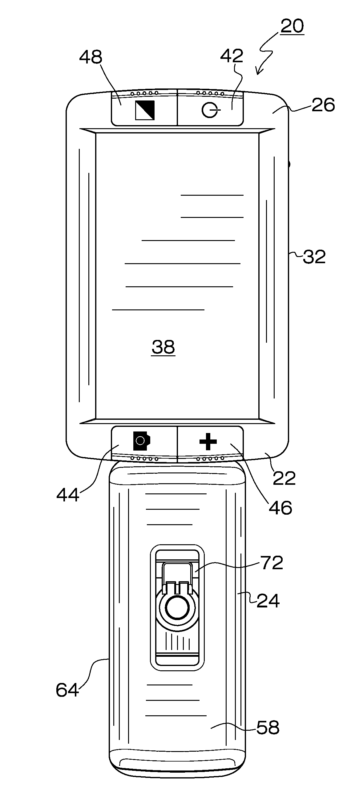
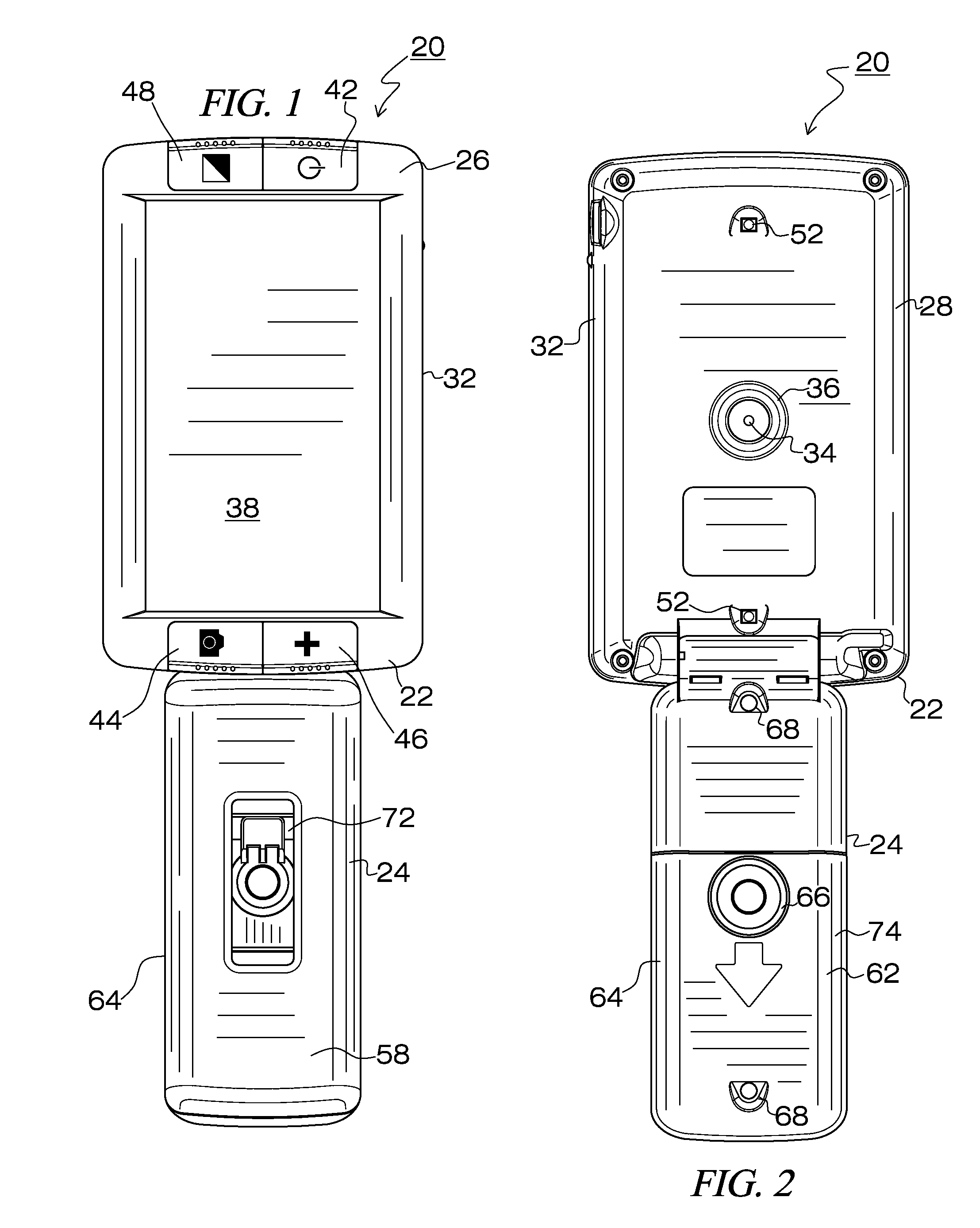
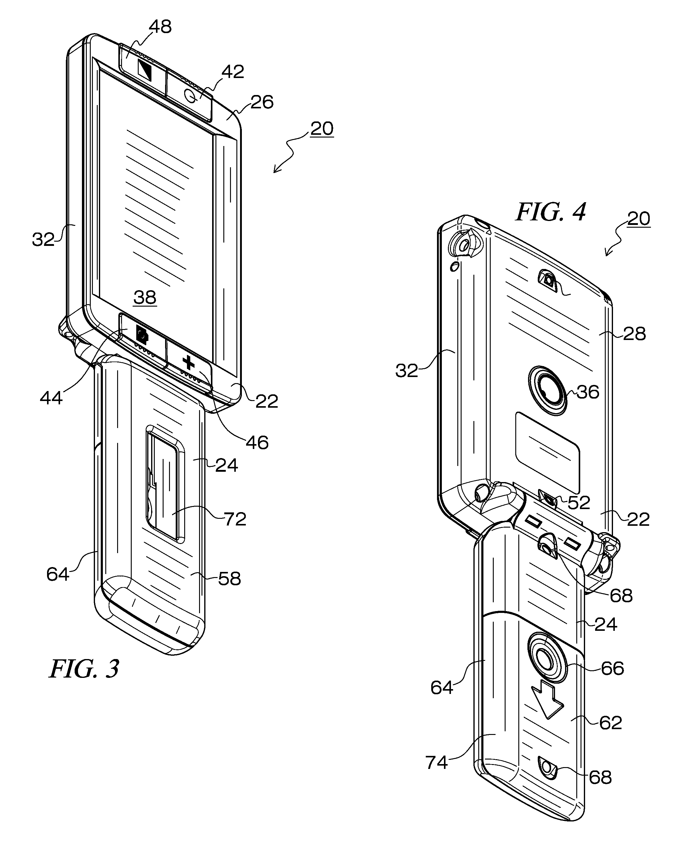
[0053]The present invention relates to a magnifier device for use by blind or low vision users. The magnifier includes a camera that can display enlarged images of target objects for viewing by the user. The magnifier device further includes a handle that is pivotally interconnected to a housing to thereby allow the device to be configured in a number of different configurations. The various features of the present invention, and the manner in which they interrelate, will be described in greater detail hereinafter.

[0054]With reference to FIGS. 1-4, the housing 22 and interconnected handle 24 of the magnifier 20 are illustrated. These components are preferably formed from an impact resistant plastic, such as an acrylonitrile butadiene styrene (ABS) plastic, or an equivalent thereof. Handle 24 and housing 22 are engaged with one another about an axis to thereby permit rotation of handle 24. As noted more fully hereinafter, magnifier 20 takes on various configurations based upon the an...


PUM


Abstract

Disclosed is a magnifier for use by blind or low vision users. The magnifier includes a camera, such as a CMOS image sensor, that displays enlarged images upon a screen for easy viewing. The magnifier further includes a handle that is pivotally interconnected to a housing to allow for handheld use in a variety of different configurations.

Description

RELATED APPLICATION DATA[0001]This is a continuation-in-part of co-pending application Ser. No. 12 / 235,182 filed on Sep. 22, 2008 and entitled “Portable Multi Position Magnifier Camera”, the contents of which are fully incorporated herein by reference.BACKGROUND OF THE INVENTION[0002]1. Field of the Invention[0003]This invention relates to a magnification device for individuals with low vision. More particularly, the present invention relates to a handheld magnification device that has a variety of discrete configurations.[0004]2. Description of the Background Art[0005]The use of electronic magnifiers for low vision users is known in the art. To date, however, these magnifiers have been heavy, bulky, and cumbersome to use. Additionally, many of these magnifiers have only one mode of operation, a mode that requires the user to hold the device at a fixed distance above the object being viewed. Prior art magnifiers also suffer from lack portability, which is problematic for users who m...

Claims


Application Information

Patent Timeline
Patent Type & Authority Applications(United States)
IPC IPC(8): H04N5/222H04N5/225
CPCH04N1/00129H04N5/2252H04N5/23296H04N2101/00H04N5/23293G02B25/005H04N23/51H04N23/69G03B17/563H04N5/2628H04N9/64
Inventor RODRIQUEZ, CARLOS M.MURPHYTUNKIS, WALDEMARCONARD, TODDGOLDENBERG, MICHAELMCDANIEL, JEFFREY
Owner FREEDOM SCI
Why Eureka
Try Eureka